


INTRODUCTION
Pedicle screw fixation (PSF) facilitates fusion and correction angles in spinal surgery [1]. However, PSF has an observed medial pedicle violation rate of 2.5% to 8.3% [2-4], which may lead to damage of the spinal cord and spinal nerve roots. Although fluoroscopy is commonly utilized to guide proper placement of the pedicle screws in PSF, neural damage caused by medial pedicle violation can still occur. Fluoroscopy also exposes both the surgeon and the patient to a non-negligible level of radiation, and it could cause various cancers, skin necrosis, lens injuries, and so on [5-10].
Triggered EMG (t-EMG) is used to verify appropriate screw placement during the PSF procedure, potentially reducing the need for constant fluoroscopic guidance. For t-EMG to produce accurate results, it is essential that each part of its electrical circuit has a consistent electroconductive property [11,12]. Electrical resistance importantly influences the reliability of t-EMG monitoring [1]. If the electrical resistance of the screw is significantly higher than that of other parts of the electrical circuit, the stimulation threshold required for detecting neural injury would be higher than expected. This elevated requirement of stimulation threshold can lead to a false verification of proper screw placement when pedicle wall penetration has occurred [12]. Currently, pedicle screws are made of titanium alloy, which is mostly Ti-6Al-4V, with an International Annealed Copper Standard (IACS) percentage of only 1.01% (annealed copper: 100% IACS percentage) [11-13]. Donohue et al. [1] reported that titanium alloy pedicle screws had a higher electrical resistance than that of stainless-steel pedicle screws, along with a large variation in conductivity. In a meta-analysis evaluating the diagnostic accuracy of t-EMG monitoring in operations involving titanium screws, Lee et al. [14] found low sensitivity of the test in both thoracic (0.41) and lumbar spine surgeries (0.55). This physical property of titanium alloy makes it challenging to determine the proper current thresholds needed to detect pedicle breaches, and lowers the sensitivity of t-EMG testing.
In contrast, gold has a 70% IACS rating making it an excellent electrical conductor (4.10×10⁷ siemens/m vs. Ti-6Al-4V at 5.62×10⁵ siemens/m) [11]. We explored the utility of gold as an electrical conductor to help overcome the inherent limitations of titanium in obtaining accurate t-EMG results. To do so, we developed 2 types of modified screws, one with a gold lead inserted internally (type I) and one with a gold lead placed externally (type II). The neuromonitoring pedicle screws described in our study were termed “Neuro-PS” based on the function of these screws in t-EMG testing. Our study used an electrical simulation model to analyze the electrical property and a pig model to analyze the neurophysiologic property of these 2 types of the Neuro-PS as compared to the conventional titanium screw.
MATERIALS AND METHODS
1. Designs and Manufactures of Neuromonitoring Pedicle Screw (Neuro-PS)
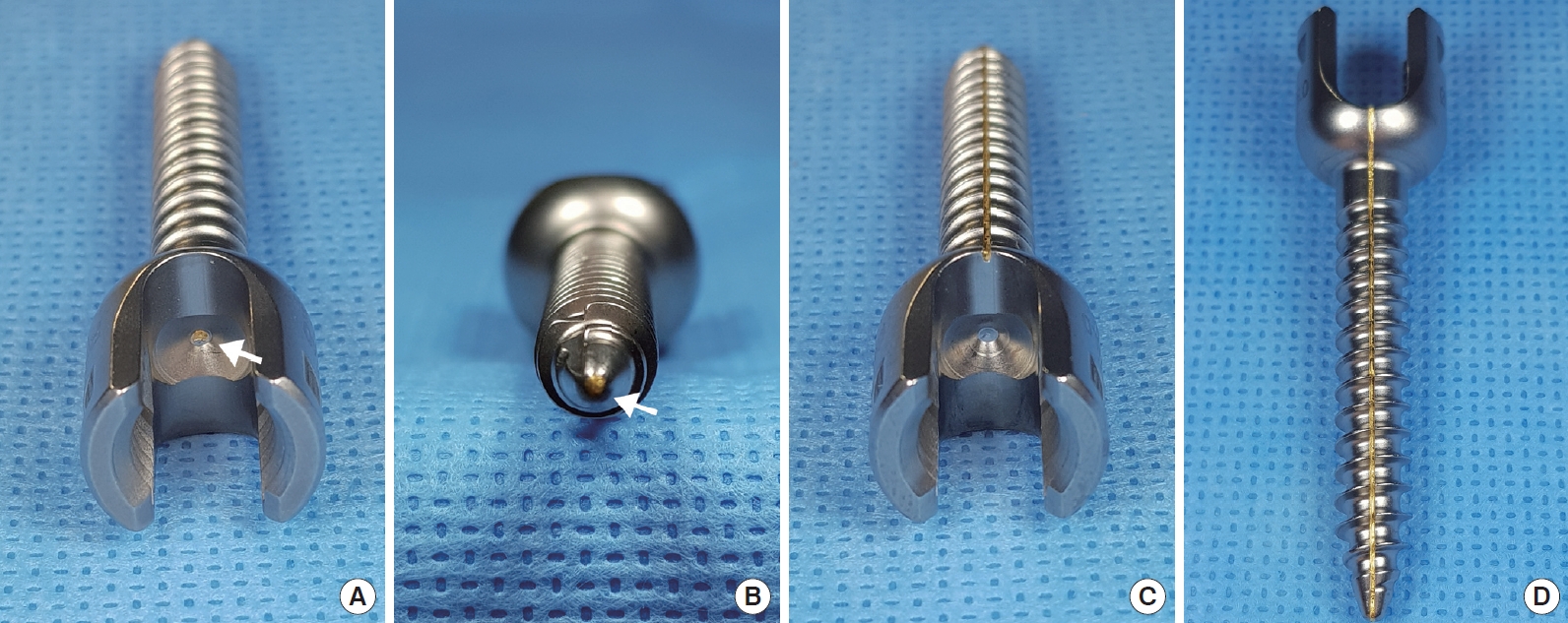
The Neuro-PS was a modification of the control screw, which was constructed from Ti-6Al-4V (FDA approved, LnK Spinal Fixation System, L&K Biomed, Seoul, Korea). Fig. 1 shows the structure of the type I and the type II Neuro-PS. In the type I Neuro-PS (internal lead type), a gold lead with a diameter of 0.5 mm was inserted through the center of the control screw (Fig. 1A, B). In the type II Neuro-PS (external lead type), a 0.5-mm diameter gold lead was placed on the surface of a control screw (Fig. 1C, D). All screws were monoaxial for the experiments since electrical resistance measurements could be influenced by the head motion of a polyaxial screw [12].
2. Resistance Measurements of Screws
The resistance measurements for the 2 types of the Neuro-PS and the control screw were recorded in air and bone. We used a 4-wire (Kelvin) resistance measurement method, which can deembed parasitic resistances from connecting wires and probing tips. We measured the resistance of 5 screws per screw type in 3 different screw sizes (4.5 mm× 40 mm, 6.5 mm× 40 mm, 6.5 mm× 50 mm) for the type I and the type II Neuro-PS and for the control screw. The screw resistance measurements in bone were taken with the screws embedded in human bone harvested from a cadaver donor. Because Ti-6Al-4V spontaneously forms a native oxide layer upon exposure to oxygen, we performed resistance measurements on the control screws after removing the native oxide layer by mechanical scrubbing. For the measurements of the Neuro-PS, 2 exposed ends of the gold lead on the head and tip of the screw were connected to the probe tips. The probe tip’s diameter was smaller than that of the gold lead, allowing for a direct point of contact. For the simulation, a 1-ampere current was applied to one end of the gold lead, while the other end was connected to the ground. Thus, the voltage across the screw directly translated to the resistance.
Also, we used a computer simulation to analyze the theoretical electrical resistance and charge distribution value of the screws. This simulation could achieve a result closer to the theoretical resistance by minimizing the errors associated with measurement environments, such as humidity, temperature, oxygen concentration in air, and so on. The resistance value and electrical charge distribution value measurements were calculated using the COMSOL Multiphysics simulation software (COMSOL, Inc., Burlington, MA, USA).
3. Neurophysiologic Test in the Pig Model
Animal research was approved by the president of the Laboratory Animal Center, Daegu-Gyeongbuk Medical Innovation Foundation (DGMIF) after being reviewed by the DGMIF Animal Care and Use Committee (DGMIF-17062201), and all animal experiments were conducted in accordance with the Regulations for Animal Experimentation of the DGMIF. We tested the electrophysiologic function of these screws on 2 Yukatan minipigs weighing 25±0.5 kg. After sedation with an intramuscular injection of alfaxalone and xylazine, the pigs were intubated, and general anesthesia was maintained with isoflurane and oxygen without administration of neuromuscular blockade agents. The pigs were ventilated throughout the procedure, and vital signs were continuously monitored.
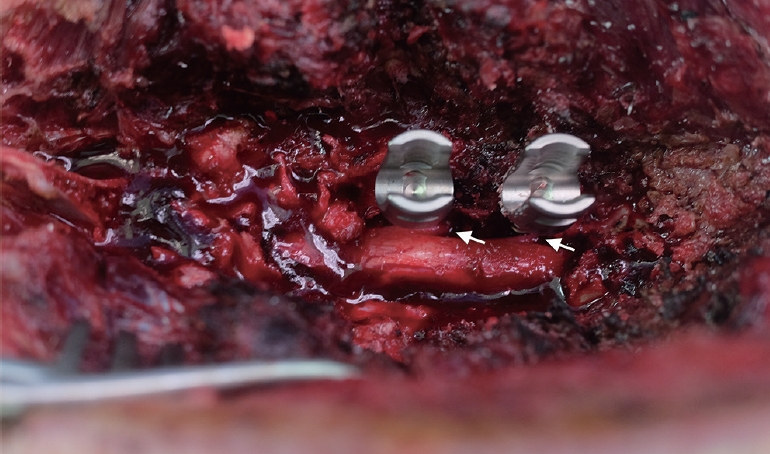
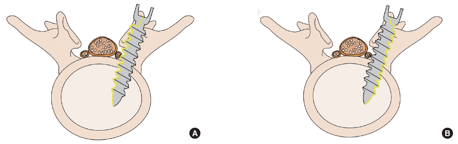
The lumbar spine (L) was subperiosteally exposed from levels L3 to L6 though a midline posterior longitudinal incision. Next, a total laminectomy was performed from L3 to L6 to expose the thecal sac and the L3–6 exiting roots. We penetrated the medial pedicle wall using the Neuro-PS and control screws, which measure 4.5 mm in diameter× 40 mm in length, to make bilateral contact with the exiting roots between L3 and L6 (Fig. 2). The stimulation thresholds were recorded at each vertebral level. Pairs of 70-mm-long monopolar EMG needle electrodes (NIM-Spine subdermal needle electrode; Medtronic Xomed, Jacksonville, FL, USA) were placed bilaterally in the rectus femoris, vastus lateralis, tibialis anterior, and gastrocnemius muscles (innervated by the L3, L4, L5, and L6 root, respectively). Stimulation was performed with a hand-held nerve stimulator (monopolar probe; Medtronic Xomed) via a cathode that was placed on the head of the screw. NIM-Spine system (Medtronics, Memphis, TN, USA) was used for stimulation and recording of the t-EMG values. Constant current stimulation (rate of 1 Hz per 0.3 msec) was applied in an ascending method (1.0 mA to 15 mA) until a repeatable compound motor action potential was obtained from the respective muscles. Recording and filtering parameters were 10 Hz for low frequency and 2,000 Hz for high frequency filtering with a time base of 50 msec/division and display sensitivity 50 µV/division. The stimulation intensity (threshold) required to evoke a measurable response above 0.1 mV was recorded. Four values were measured from one screw, because both pedicles in same lumbar level were used in 2 pigs except type II Neuro-PS. We recorded the stimulation thresholds of the type II Neuro-PS under 2 different conditions according to the location of the external lead. The “type II Neuro-PS under the lead-nerve contact condition” occurred when the external lead of the type II Neuro-PS was located at the interface between the screw and the nerve root (Fig. 3A). The “type II Neuro-PS under the lead-nerve noncontact condition” occurred when the external lead was located at the opposite face of the interface between the screw and the nerve root (Fig. 3B). Upon completion of data acquisition, the animals were euthanized with an injection of intravenous potassium chloride while still under general anesthesia.
4. Statistical Analysis
All statistical analysis was completed using IBM SPSS Statistics ver. 19.0 (IBM Co., Armonk, NY, USA). Data were expressed as mean±standard deviation. Univariate analysis was performed to determine the differences in the measurements of the control, type I, and type II groups. The pig model t-EMG test values were analyzed using the Kruskal-Wallis test and the Mann-Whitney U test. A p-value of < 0.05 was considered significant.
RESULTS
1. Electrical Resistances of Screws
The electrical resistance measurement values categorized by the length and the diameter of the screw are summarized in Table 1. With a same diameter, a longer length of screw was associated with an increase in the resistance value of all groups (control, type I, and type II). Also, a smaller diameter was correlated with an increase of resistance in same length. Intriguingly, these differences of resistance value according to the diameter or length of screw were larger in control group. The resistance of 4.5 mm×40 mm and 6.5 mm× 50 mm were 96±7.08 mΩ and 102±6.38 mΩ in air, which was 5.9% difference. In contrast, the Neuro-PS type I and II showed the 1.8% (4.5 mm× 40 mm: 5.4±0.51 mΩ; 6.5× 50: 5.5±0.42 mΩ) and 3.0% difference (4.5 mm× 40 mm: 3.2±0.61× mΩ; 6.5× 50: 3.3±0.52× mΩ) in air, respectively.
The electrical resistances of the Neuro-PS were remarkably lower than those of the control screw in the 3 different screw size groups in bone conditions. The electrical resistance of the type II Neuro-PS in bone was lower than that of the type I Neuro-PS in all screw size groups. The type I Neuro-PS showed minimal differences in resistance between air and bone. The type II Neuro-PS tended to have a decreased resistance in bone as compared to air, although the differences were not statistically significant.
2. Comparison Between Electrical Resistances in Air Condition and Calculated Resistances
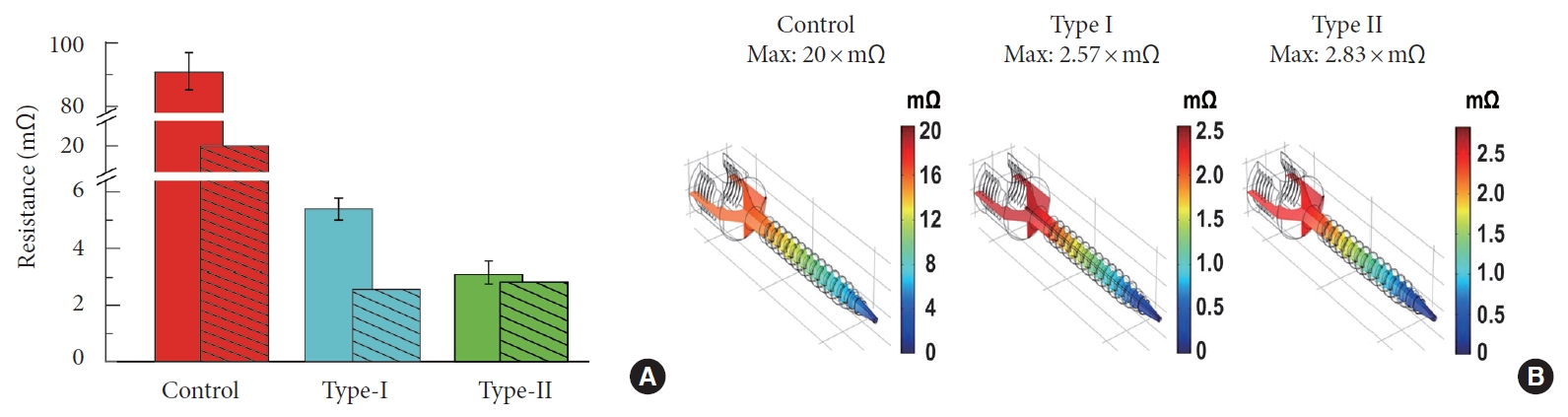
The bars without fill patterns in Fig. 4A show the resistance of the 6.5× 40-mm screw size groups. The average resistance of the control screw was 91±4.98 mΩ. The average resistances of the type I and the type II Neuro-PS were 5.4±0.43× mΩ, and 3.1±0.43 × mΩ, respectively (Table 1). The bars with fill patterns in Fig. 4A represent resistances calculated by the COMSOL Multiphysics simulation. The calculated resistance of the control screw, the type I Neuro-PS, and the type II Neuro-PS were 20× mΩ, 2.57× mΩ, and 2.83× mΩ, respectively. The resistances of the type I and the type II Neuro-PS were an order of magnitude smaller than that of the control screw in both the actual and the simulation measurements. Fig. 4B shows the simulated voltage distribution across the screws. The calculated resistance values fell within the range of the standard error of the measured resistance values, suggesting good agreement of the two.
3. Electrical Charge Distribution Values of Screws
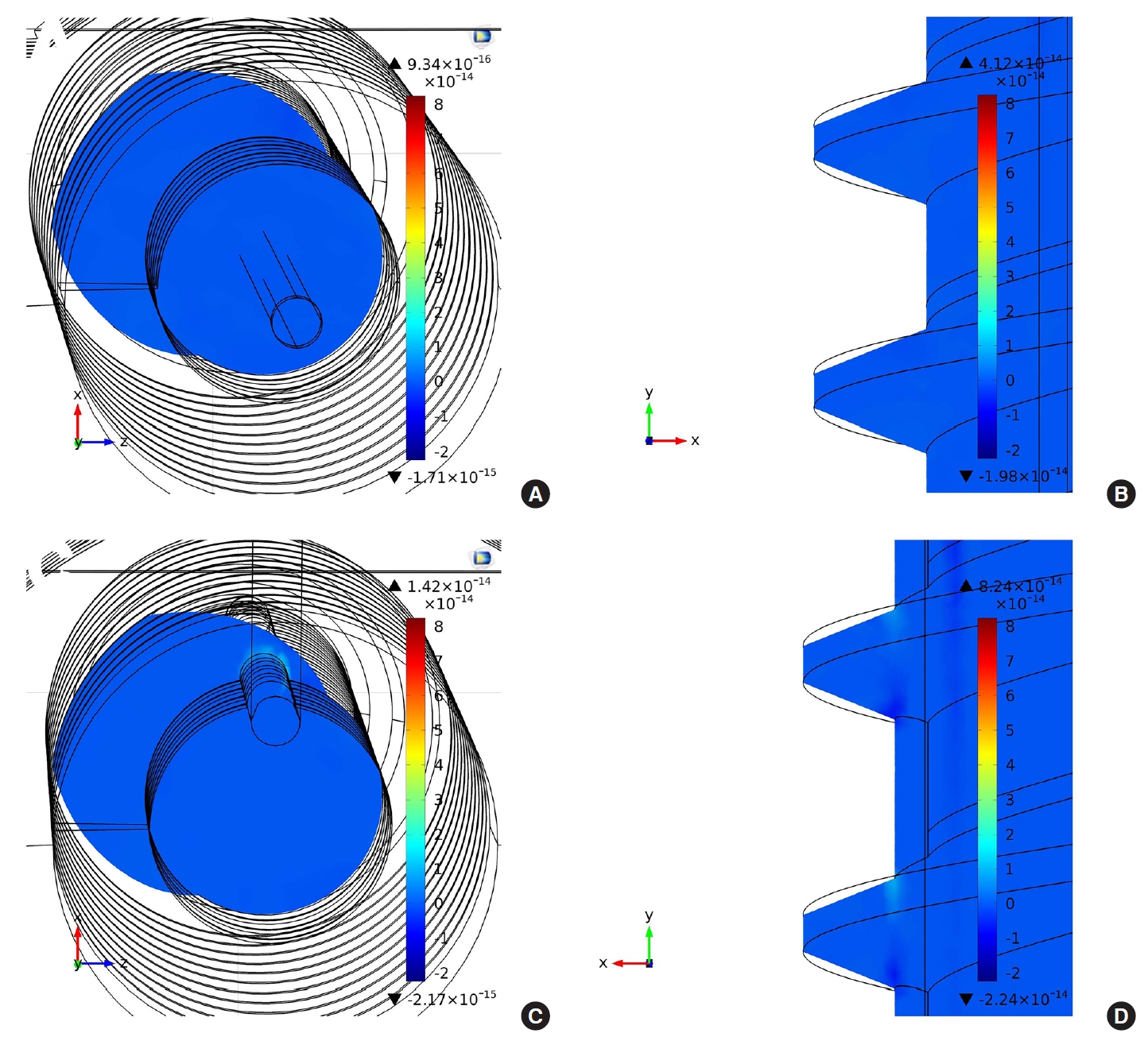
The volume charge density (C/m3) distribution of each screw was also calculated by the COMSOL Multiphysics simulation. The volume charge density can translate into a resistance that can provide the local resistance of the screws. Fig. 5A and C show the volume charge density distribution in the cross-section of type I and type II Neuro-PS, respectively, when one microampere of current flows through the screws. In the figures, the smallest circles represent the gold lead electrode, and the other black lines are the structure of the screws. The volume charge density of the type I Neuro-PS shows a uniform distribution over the cross-section, whereas that of the type II Neuro-PS shows a nonuniform distribution and a higher density on the surface of the gold lead electrode. It indicates that more current flows on the surface of the gold lead electrode than other parts of the screw, allowing the type II Neuro-PS to provide a smaller stimulation threshold when the gold lead electrode is in contact with the nerve. Fig. 5A and D show the volume charge density distribution in a midsagittal section of the type I and type II Neuro-PS, respectively. Similar to the volume charge densities in the cross-sections, the type I Neuro-PS shows a uniform volume charge distribution and the type II Neuro-PS shows a higher volume charge density on the thread near the gold lead electrode.
4. Neurophysiologic Analysis in Pig Model
The mean stimulation thresholds of the screws at each vertebral level are summarized in Table 2. In a recent systematic review paper on the use of t-EMG to detect misplaced pedicle screws, a mean stimulation threshold of 10–12 mA provided the most accurate testing parameters for detecting misplaced screws [15]. The mean stimulation threshold for the type I Neuro-PS was 6.38±0.8 mA and for the control screw was 6.69±0.94 mA. The mean stimulation threshold for the type II Neuro-PS under the lead-nerve contact condition was 2.94±0.57 mA, and for the type II Neuro-PS under the lead-nerve noncontact condition was 6.56±0.73 mA. The type II Neuro-PS under the leadnerve contact condition was more conductive than the other screws, including the type II Neuro-PS under the lead-nerve noncontact condition (p < 0.001). However, the type II Neuro-PS under the lead-nerve noncontact condition demonstrated a similar mean stimulation threshold as compared to the control screw. These results demonstrated that the type II Neuro-PS had a higher electrical conductivity only when the external lead met the root directly. The type I Neuro-PS had a lower mean threshold value than both the control screw and the type II Neuro-PS under the lead-nerve noncontact condition, but the differences were not statistically significant.
DISCUSSION
Our study demonstrated that the Neuro-PS had a lower electrical resistance as compared to the conventional screw due to the incorporation of the gold component. The resistance of the Neuro-PS could be further lowered by increasing the area of the gold lead. However, according to our result, this low electrical resistance of the Neuro-PS was not a factor influencing the low stimulation threshold of the t-EMG test in the pig model. Through the type II Neuro-PS result in the pig model, we learned that the decisive factor for a lower stimulation threshold in comparison with the conventional screw was whether the external lead made contact with the nerve or not. We found theoretical background for this finding from our COMSOL Multiphysics result of the charge distribution. In the COMSOL Multiphysics results, calculated resistance of type I Neuro-PS was lower than that of type II Neuro-PS. However, only the type II Neuro-PS showed asymmetric charge distribution around the gold lead compared to the screw body. In other words, asymmetric charge distribution at the screw body surface is much more important than resistance of the screws itself for a lower stimulation threshold of the t-EMG test.
The type II Neuro-PS, which had an external lead, showed different characteristics compared to other screws that were important. The location of the gold lead depended on the axial rotation of the type II Neuro-PS. The type II Neuro-PS under the lead-nerve contact condition had a significantly lower mean stimulation threshold than that of the other screws. However, the mean stimulation threshold of the type II Neuro-PS under the lead-nerve noncontact condition was not significantly different than that of the other screws. These results indicate that although the electrical resistance of the type II Neuro-PS was remarkably lower than that of the control screw, there was no significant difference in the stimulation threshold measurements in t-EMG testing when the external gold lead lacked contact with the nerve root.
The feature of the type II Neuro-PS can be effectively applied in clinical practice to check contact with the nerve root during the t-EMG test. Among the variant types of pedicle breach by screw, the type which is the most dangerous and requires reinsertion is a screw that directly deflects or pierces the rootlets. As the surgeon can easily recognize the exact location of external lead through the exposed tip of the lead at the screw head, the surgeon can vary the position of the screw to test for contact with the nerve root by turning the screw to position the external lead towards the medial side during the t-EMG. Additionally, the sensitivity of neuromonitoring using the type II Neuro-PS could be improved by varying the width and number of the gold lead.
The type II Neuro-PS may also be a useful assistive tool for computer-assisted robotic surgery during percutaneous PSF [16,17]. Using a real-time tracking system based on a preoperative performed computer tomography image, robotic surgery can provide more accurate PSF than conventional manual surgery. However, up-to-date computer-assisted robotic surgery does not have a self-judgement ability in the true sense of the word. Screw fixation through this technology only delivers pinpoint accuracy and consistency with a preoperatively planned trajectory. As there is a difference between the real spine and preoperatively obtained spine images, screw malposition under this technology can occur, albeit at a low rate (1.1%) [18]. For this reason, the surgeon has to decide whether screw fixation by robotic surgery should continue when the screw penetrates the pedicle. However, if the type II Neuro-PS with the t-EMG monitoring is applied, the robot can make decisions under accurate neuromonitoring on behalf of the surgeon in the same situation. This excellent collaboration would likely make the malposition rate lower than that of computer-assisted robotic surgery alone.
We chose the gold as metal for Neuro-PS for a couple of reasons. First, gold is excellent electrical conductor as stated in introduction. In a similar study using a pig model conducted in 2012 by Spain researchers, mean electrical threshold was 4.9±1.9 mA when the screw was placed in contact with the dural sac [19]. Mean electrical threshold of the type II Neuro-PS in same situation was 2.94±0.57 mA. Gold of the type II Neuro-PS makes this difference. Second, gold is a highly polarized electrode. It forms no native oxide layer on the surface, but can accommodate a large amount of injected charge on the electrochemical double-layer capacitor before initiating Faradaic reactions. It is known that Ti-6Al-4V forms a highly stable bi-layered oxide film on the surface consisting of a porous outer layer and a barrier inner layer. Scromeda and Katsube [20] found that the area for the normalized double-layer capacitance of gold was 30.9 μF/cm2, which was about 6 times larger than the total capacitance of the native oxide on titanium alloy. This characteristic of gold made the resistance values of the Neuro-PS closer to the stimulation values in COMSOL analysis. Third, gold is harmless and does not oxidize in the human body, making it promising for future clinical use.
Our study has limitations. First, our study did not examine the effect of the screws on t-EMG testing involving the cervical or the thoracic spine, which have different anatomical characteristics compared to that of the lumbar spine. Second, we did not examine the mechanical strength of the Neuro-PS. In the present study, we made a small niche on the surface of a conventional screw and a 0.5-mm diameter gold lead, which could influence the mechanical strength, was placed in a niche for type II Neuro-PS. The present study is sort of a pilot study examining the usefulness of gold to lower the stimulation threshold. We already made a new Neuro-PS using gold plate, not gold lead on the basis of this study. Gold plated Neuro-PS showed equivalent mechanical strength compared to conventional pedicle screw. We are preparing biomechanical study of this new Neuro-PS. Third, we did not use the multiaxial screw, which is the most widely used screw. However, the aforementioned new Neuro-PS is multiaxial screw and the surgeon can still easily recognize the exact location of external gold plate through the exposed end of the gold at the proximal shaft, not at the screw head. Fifth, we did not analyze the cost effectiveness of Neuro-PS compared to conventional titanium screw. Using gold for screw can lead to additional cost to manufacture the screw. We are estimating that a cost to manufacture the new Neuro-PS is likely to rise by 15% compared to the conventional screw.
CONCLUSION
The Neuro-PS showed a significantly lower electrical resistance than that of the conventional titanium screw. However, in t-EMG testing using a pig model, only the type II Neuro-PS under the lead-nerve contact condition showed a remarkably lower mean stimulation threshold compared to that of the other screws. These results suggest that the type II Neuro-PS may provide more accurate t-EMG measurements than that of the conventional screw during PSF. In conclusion, we think that the concept and technology applied to Neuro-PS can improve the safety with reducing nerve injury during PSF.