Evaluation and Comparation of a Novel Surgical Technique and Hemivertebra Resection to the Correction of Congenital Cervical Scoliosis in Lower Cervical and Cervicothoracic Spine
Article information

Abstract
Objective
To report concave-side distraction technique to treat congenital cervical scoliosis in lower cervical and cervicothoracic spine. To evaluate and compare clinical and radiographic results of this procedure with classic hemivertebra resection procedure.
Methods
This study reviewed 29 patients in last 13 years. These patients were divided into convex-side resection group (group R) and concave-side distraction group (group D). Radiographic assessment was based on parameter changes preoperatively, postoperatively and at last follow-up. Demographic data, surgical data and complications were also evaluated and compared between the 2 groups.
Results
In group R, mean age was 8.9 ± 3.3 years and follow-up was 46 ± 18 months. Operation time and blood loss averaged 500 ± 100 minutes, 703 ± 367 mL. In group D, mean age was 9.9 ± 2.8 years and follow-up was 34 ± 14 months. Operation time and blood loss averaged 501 ± 112 minutes, 374 ± 181 mL. Structural Cobb angle was corrected from 29.4° ± 12.5° to 5.3° (2.1°–18.1°) (p = 0.001) and 33.7° ± 14.1° to 12.8° ± 11.4° (p < 0.001) in groups R and D. Compensatory Cobb angle had a spontaneous correction rate of 59.6% (40.0%–80.8%) and 59.7% ± 23.0% in groups R and D. Mandibular incline, clavicle angle and spine coronal balance were significantly improved at last follow-up in both groups. All correction rates were not statistically different between groups. However, group D had significant less blood loss (p < 0.001) and operation time (p = 0.004) per vertebra than group R. Seven patients developed C5 nerve root palsy and recovered by 6 months of follow-up.
Conclusion
Both surgical procedures are safe and effective in correcting congenital cervical scoliosis. But concave-side distraction technique has less blood loss and time-consuming during surgery, which provides a better option for the treatment of congenital cervical scoliosis.
INTRODUCTION
Congenital cervical scoliosis is caused by multiple defects of segmentation or formation of vertebra, including hemivertebra, wedged vertebra, butterfly vertebra, block vertebrae, and unilateral bar [1]. Major curve in cervical region usually associates with proximal thoracic compensatory curve [2]. These deformities usually appear in children and adolescents with undesired appearance, including head tilt, shoulder imbalance and asymmetrical facial development [3], which often trouble their patients and families. Pain or neurologic deficits due to the deformity are rare in the beginning and these symptoms usually occur later secondary to instability and degenerative arthritis in the hypermobile segments adjacent to the anomaly [4].
Deformed vertebra in cervical region is unusual and the incidence is low compared to that in the thoracic and lumbar regions [5]. This anomaly is usually associated with additional deformities and the most common is congenital synostosis of 2 or more cervical vertebras, known as Klippel-Feil syndrome [6]. The potential of compensation in adjacent spine regions is low and conservative treatment, for example brace treatment, is unable to influence the unbalanced spinal growth [7]. Because of the complex anatomy of deformed vertebra and adjacent structures, such as nerve roots and vertebral arteries, it greatly increases the difficulty of surgical correction. Thus, surgical treatment was limited to posterior fusion in situ without scoliosis correction for a long time [8,9]. Until 2005, Ruf et al. [5] reported a combined approach to resect hemivertebra to correct cervical scoliosis. Currently, hemivertebra resection is a widely accepted surgical technique to correct congenital cervical scoliosis [5,10-14] and was adopted since 2009 in our department. Since 2016, we developed a novel surgical technique to treat congenital cervical scoliosis. Instead of hemivertebra resection on convex side, we distract and fill the deficiency on concave side, The purpose of this study is (1) to report a novel surgical technique instead of hemivertebra resection and (2) to evaluate and compare the clinical and radiological outcomes between the 2 surgical techniques.
MATERIALS AND METHODS
1. Inclusion and Exclusion Criteria
Inclusion criteria was patients with the presence of torticollis caused by congenital cervical scoliosis (defined as a Cobb angle of > 10°) in lower cervical and cervicothoracic spine; Operation and follow-up were performed in our hospital. The indication for surgery is patients with severe disfiguring deformity or patients with proven or expected deterioration deformities.
Exclusion criteria included (1) Patients with congenital cervical scoliosis caused by deformed vertebra in cranial-cervical junction or other causes of torticollis appearance, such as muscular torticollis, ocular torticollis, neurogenic torticollis, etc.; (2) Patients with other spinal deformity or disease, such as cervical kyphosis or kyphoscoliosis, congenital deformity of middle and lower thoracic spine, lumbar spine, ankylosing spondylitis, severe ossification of cervical posterior longitudinal ligament, etc.; (3) Cervical infectious diseases, cervical primary, or metastatic tumor; (4) Have a history of spinal trauma or surgery; (5) Imaging data are incomplete or follow-up time less than 24 months.
2. General Data
We reviewed 76 cases from congenital cervical scoliosis database in our department from January 2009 till now. According to inclusion and exclusion criteria, 29 patients were included in this study. According to different surgical procedures, we divided these 29 patients into 2 groups, convex-side resection group (group R), which was performed before 2016, and concave-side distraction group (group D), which was performed after 2016. These 2 surgical procedures had same surgical indication. The details of patients’ demographic and operative data were recorded in Tables 1 and 2.
Demographic data for patients
Surgical details for patients
This study protocol was approved by the Medical Science Research Ethics Committee of the Peking University Third Hospital (approval number: 2015269) and written evidence of informed consent was obtained from patients’ parents.
3. Radiographic Assessment
Photos and radiographic images were captured on each patient at a relaxed standing position, with no correction of torticollis. Computed tomography (CT) was performed to provide the details of osseous malformation. Computed tomographic angiography (CTA) was used before operation to evaluate for vertebral and carotid artery malformations. Radiographic parameters were measured independently by 2 surgeons before surgery, 3 months after surgery, and at last follow-up. We recorded the average of each measurement.
On coronal reconstruction view of CT scan, we recorded structural Cobb angle, which is the large curve in the segments with vertebral deformities causing clinical asymmetry or head deviation and needs to be surgically corrected. It is shown as the angle between the lines drawn parallel to the superior endplate of the most cranial vertebra and to the inferior endplate of the most caudal vertebra in the curve.
On standing posteroanterior radiographs of the spine, we measured 4 parameters to describe scoliosis: (1) Compensatory Cobb angle, the small curve without vertebral deformities. It is compensatory to the structural curve and is shown as the angle between the lines drawn parallel to the superior endplate of the most cranial vertebra and to the inferior endplate of the most caudal vertebra in the curve; (2) Mandible incline, the angle between horizontal line and the line through mandibular angles on both sides; (3) Clavicle angle, the angle between horizontal line and the line through the clavicular distal end on both sides; and (4) Spine coronal balance, the distance between a vertical line drawn from the apex of the odontoid process and the vertical line through the midpoint of superior endplate of sacrum. The details are shown in Fig. 1.

Radiographic assessment parameters. (A) On the coronal reconstruction view of computed tomography scan, structural Cobb angle (a) is the large curve with vertebral deformities and is shown as the angle between the lines drawn parallel to the superior endplate of the most cranial vertebra and to the inferior endplate of the most caudal vertebra in the curve. (B) On the standing posteroanterior radiographs of the spine, Compensatory Cobb angle (b) is the small curve without vertebral deformities and is compensatory to the structural curve; Mandible incline (c) is the angle between the horizontal line and the line through the mandibular angles on both sides; Clavicle angle (d) is the angle between the horizontal line and the line through the clavicular distal end on both sides; Spine coronal balance (e) is the distance between a vertical line drawn from the apex of the odontoid process and the vertical line through the midpoint of superior endplate of sacrum.
All parameters were obtained from the PACS (picture archiving and communication system) of the hospital, with an accuracy of 0.1 mm or 0.1°. The postoperative correction rate was calculated using [(preoperation parameter–postoperation parameter)/preoperation parameter]× 100%.
4. Surgical Techniques
In our department, convex-side resection and concave-side distraction procedure were used before and after 2016. The details of surgical techniques were introduced as follows.
1) Preoperative preparation
A sterilized 3-dimensional (3D)-printed model was prepared to assist the surgeon to make preoperative surgical plan and recognize anatomical malformations during operation. Neurophysiological monitoring of the spinal cord was done throughout the procedure by measuring somatosensory evoked and motorevoked potentials.
2) Convex-side resection technique
Resection of the cervical hemivertebra was performed using an anterior-posterior-anterior combined approach (Fig. 2). Detailed surgical procedures were shown in previous report [15].
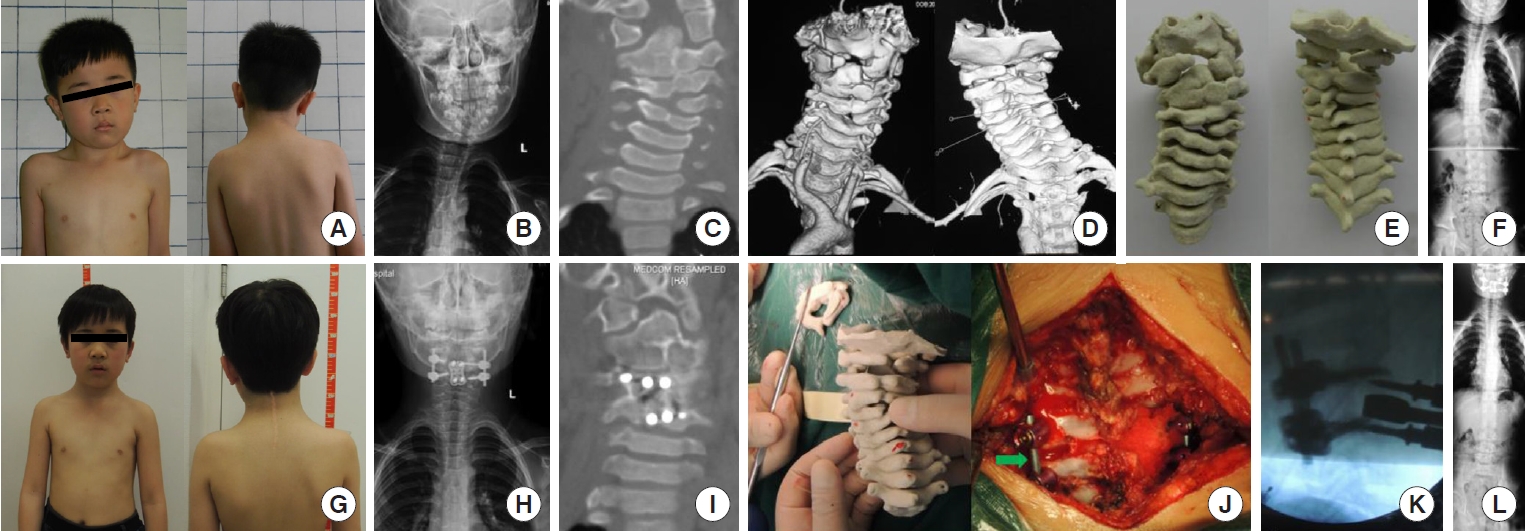
Photographs and radiographs from case 6, group R (convex-side resection group). A 6-year-old boy with left C4 fully segmented hemivertebra. (A) A preoperative photograph shows obvious torticollis and head tilt. (B, C, F) Posteroanterior radiographs and computed tomography (CT) scan on coronal reconstruction view show mandible incline angle is 6.1°, clavicle angle is 1.3° and spine coronal balance is 18.0 mm. Structural and compensatory Cobb angle are 31.6°, 25.4°. (D, E) Three-dimensional (3D) reconstruction on CT scan and 3D-printed model. (G) Photographs after surgery show obvious improved appearance. (H, I, L) Posteroanterior radiographs and CT scan show mandible incline angle is 0.4°, clavicle angle is 1.4° and spine coronal balance is 25.2 mm. Structural and compensatory Cobb angle are 7.7°, 14.7°. (J, K) Photographs show a sterilized 3D printed model is prepared to assist the surgeon in recognizing anatomical malformations during operation. A gap is showed after left C4 hemi lamina resection (green arrow) and intraoperative fluoroscopy.
The main procedures consist of 3 steps. Step 1: The hemivertebra body and adjacent discs were entirely dissected and the anterior part of transverse process was removed through an anterior approach. The vertebral artery and nerve root were exposed and protected. Step 2: The lamina, lateral mass with pedicle and the posterior part of the transverse process were removed through a posterior approach. The spinal cord, vertebral artery and nerve root were exposed. Pedicle screws and rods were placed and the gap between adjacent levels after resection was closed by bending the head to convex side under Mayfield traction. Step 3: A polyetheretherketone (PEEK) cage contained auto bone graft was placed into the intervertebral space and titanium plate was placed.
3) Concave-side distraction technique
Distraction and lateral opening on concave side to correct cervical scoliosis was also performed using an anterior-posterior-anterior combined approach (Figs. 3, 4).
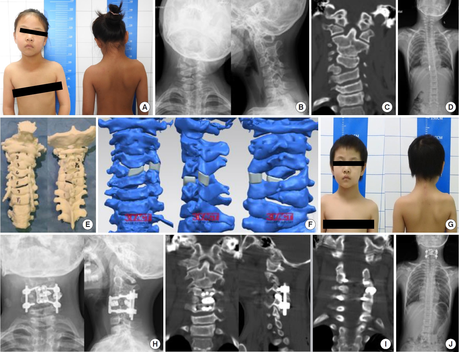
Photographs and radiographs from case 2, group D (concave-side distraction group). A 9-year-old girl with right C5 fully segmented hemivertebra and C2–3 block vertebra. (A) A preoperative photograph shows obvious torticollis and head tilt. (B–D) Posteroanterior radiographs and computed tomography (CT) scan on coronal reconstruction view show mandible incline angle is 6.3°, clavicle angle is 2.1°, spine coronal balance is 15.3 mm. Structural and compensatory Cobb angle are 35.4°, 11.0°. (D, E) Three-dimensional (3D) printed model and designed surgical plan show C5 right hemivertebra and 3D-printed metal spacers are placed between left C4–6 vertebral bodies and left C4–6 facet joint to distract concave side. (G) Photographs after surgery show obvious improved appearance. (H, I, J) Posteroanterior radiographs and CT scan show mandible incline angle is 0.1°, clavicle angle is 5.2°, spine coronal balance is 7.2 mm. Structural and compensatory Cobb angle are 4.9°, 1.7°. Two 3D-printed metal spacers between left C4–6 vertebral bodies and left C4–6 facet joint are placed as surgical plan.
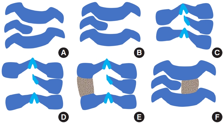
Diagram of each surgical process for concave-side distraction technique. (A) Anterior approach, the initial status before surgery. (B) Soft tissue release on intervertebral disc and uncovertebral joint. (C) Posterior approach, the initial status before surgery. (D) Soft tissue release on facet joint capsule and ligamentum flavum. (E) Place a 3-dimensional (3D)-printed customized spacer between the facet joint on concave side to correct scoliosis. (F) Anterior approach, place a 3Dprinted customized spacer between the vertebral bodies on concave side to correct scoliosis.
Step 1: Patient was placed in supine position and then given general anesthesia. Conventional anterior cervical approach was used to reach prevertebral space. According to preoperative plan, the intervertebral discs and cartilage plate were removed by curettage and nucleus pulposus forceps. Musculi longus cervicis was dissected subperiosteally and released to the lateral side of uncovertebral joint. The upper or lower level disc was excised and the epiphyseal plates of the upper and lower segments were scraped off to the lateral side of uncovertebral joint. Posterior longitudinal ligament was released and drainage was placed and the incision was closed temporarily.
Step 2: Patient was then placed in the prone position. The lamina, lateral masses on both sides and facet joints were exposed. Pedicle screws were placed in the adjacent upper and lower segments under navigational guidance and fixation rods were placed. After pedicle screws were distracted on concave side under simultaneous Mayfield traction, a valley gap between facet joint on concave side was created. The cartilage of the facet joint was completely removed and cortical bone was roughened. According to the degree of distraction, a well-reshaped and polished PEEK cage or a 3D-printed customized titanium alloy spacer was placed between the upper and lower facet joints and make sure it was in close contact with the cortical bone of the facet joints. After satisfactory position was confirmed under fluoroscopy, nail rod system was locked. Allograft bone grafting was performed around cage, on facet joint, lateral mass, and lamina. Drainage was placed and the incision was closed.
Step 3: Then the patient was placed in supine position for anterior fusion with plate fixation. The upper and lower cartilage plates of the adjacent vertebral bodies were completely removed and the cortical bone was roughened. A PEEK cage or a 3D-printed customized titanium alloy spacer was grafted into the intervertebral space on concave side, above which a titanium plate was placed. At last drainage was placed and the incision was closed.
4) Postoperative management
After surgery, patients were given sufficient analgesia (intravenous nonsteroidal anti-inflammatory drugs and analgesic drugs combined with weak opioids) and prevention of infection (cephalosporin, intravenous infusion for 48 hours). When the drainage flow was less than 50 mL/24 hours, the drainage tube was removed. After the anterior and posterior drainage tubes were removed, the patient was able to move to the ground. Postoperative neck brace braking was not required but within 6 weeks after operation, collar protection should be applied when going out for activities.
5. Statistical Analysis
An adaptation of Shapiro-Wilk test was used to examine whether the data were normally distributed. Continuous variables with normal distribution were presents as mean± standard deviation; nonnormal variables were reported as median (interquartile range). Categorical variables were analyzed by chi-square test. Mean of 2 continuous normally distributed variables between the 2 groups were compared by 2-independent samples t-test; nonnormal variables were assessed with the Mann-Whitney U-test. Mean of 2 continuous normally distributed variables before and after operation were compared by paired sample t-test in each group; nonnormal variables were assessed with Wilcoxon sign rank test. The data were analysed by IBM SPSS Statistics ver. 20.0 (IBM Co., Armonk, NY, USA). A p-value of <0.05 was considered significant.
RESULTS
1. Demographic and Operative Data in Each Group
No patient presented neurologic deficit before surgery in these 2 groups. Convex-side resection group (group R) contained 15 patients (7 males and 8 females) with an average age of 8.9± 3.3 years (range, 4−15 years) at surgery. All cases in group R were resected one hemivertebra or wedged vertebra totally or partially. The mean operation time was 500± 100 minutes (range, 279–670 minutes) with an average blood loss of 703± 367 mL (range, 100–1,500 mL). The mean follow-up was 46± 18 months (range, 24–72 months) (Table 1). Concave-side distraction group (group D) contained 14 patients (8 males and 6 females) with an average age of 9.9± 2.8 years (range, 6–14 years) at surgery. Eight patients were distracted in 1 segment and 6 were distracted in 2 segments. The mean operation time was 501± 112 minutes (range, 326–660 minutes) with an average blood loss of 374± 181 mL (range, 110–600 mL). The mean follow-up was 34± 14 months (range, 24–60 months) (Table 1).
Because of the different number of surgical segments in 2 groups, total operation time and total blood loss during surgery cannot make good comparison between groups. Except for the procedure of resection and distraction, pedicle screw placement is the most influential procedure for intraoperative bleeding and operation time. Thus, these 2 data were divided by the number of pedicle screw placed vertebra in each patient. The vertebra of screw placement was shown in Table 2. Therefore, we obtained 2 new indicators to describe operation time and intraoperative blood loss. Operation time per vertebra was 243± 51 minutes (range, 140–335 minutes) and 181± 55 minutes (range, 101–302 minutes) in groups R and D, respectively. Blood loss per vertebra was 342± 183 mL (range, 50–750 mL) and 123± 55 mL (range, 55–250 mL) in groups R and D, respectively.
2. Correction Results in Each Group
In group R, the mean structural Cobb angle was 29.4°± 12.5° before surgery and 5.3° (range, 2.1°–18.1°) after surgery (Z = -3.408, p=0.001) with an average correction rate of 81.7% (range, 38.0%–90.3%) and 4.2° (range, 1.5°–14.6°) at the last follow-up (Z= -2.544, p= 0.057). The distal compensatory curve averaged 19.3°±11.6° before surgery and 8.7°±6.8° after surgery (t=4.129, p = 0.001) with a mean spontaneous correction rate of 59.6% (range, 40.0%–80.8%) and it was 7.7°± 6.3° at the last follow-up (t= 1.019, p= 0.325). In terms of head tilt and shoulder balance, mandibular incline was corrected from 7.4°± 5.1° to 2.5° (range, 2.1°–4.3°) (Z= -2.386, p= 0.017) and clavicle angle was corrected from 4.8°±3.2° to 1.1° (range, 0.5°–2.3°) (Z=-1.875, p=0.035). Spine Coronal balance changed from 30.3 mm (range, 18.0–46.4 mm) to 10.0 mm (range, 6.7–29.0 mm) (Z= -2.101, p= 0.036).
In group D, the mean structural Cobb angle was 33.7°± 14.1° before surgery and 12.8°±11.4 °after surgery (t=11.197, p<0.001) with an average correction rate of 66.7%±23.4% and 12.5°±11.0° at the last follow-up (t= 0.493, p= 0.630). The distal compensatory curve averaged 19.9° ± 8.6°before surgery and 8.9° ± 7.7° after surgery (t= 8.473, p< 0.001) with a mean spontaneous correction rate of 59.7% ± 23.0% and it was 8.7° ± 7.1° at the last follow-up (t= 0.819, p= 0.427). In terms of head tilt and shoulder balance, mandibular incline was corrected from 4.5°± 2.6° to 1.6° (range, 0.3°–4.4°) (Z= -2.543, p= 0.011) and clavicle angle was corrected from 4.0°±2.0° to 2.0°±1.7° (t=3.140, p=0.008). Spine Coronal balance changed from 25.9± 15.4 mm to 8.5 mm (range, 6.3–22.1 mm) (Z= -3.006, p= 0.010). Details were shown in Table 3.

Correction results for 2 groups
3. Comparasion Between Groups
In demographic and operative data, group D had less operation time per vertebra (t= 3.146, p= 0.004) and less blood loss per vertebra (t= 4.408, p< 0.001) than group R. The other data showed no statistical difference between the 2 groups. Meanwhile, there was no statistical difference in correction rate of each radiological parameter between the 2 groups (Table 4).
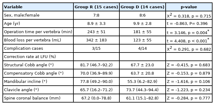
Comparison between the 2 groups
4. Complications
In group R, 3 of 15 patients developed a postoperative C5 nerve root palsy with a decrease in deltoid muscle strength. Two cases had palsy on convex side and the other one had it on concave side. In group D, 4 of 14 patients developed a postoperative C5 nerve root palsy. Two cases had palsy on convex side and the other 2 had it on concave side (Table 1). All patients were treated with conservative treatment and their symptoms were completely recovered by 6 months after the surgery. No vertebral artery injuries, dural sac tear, reoperation caused by pedicle screw malpositioning or other severe complications were observed either during surgery or the follow-up period. The bone fusion (infiltration of trabeculae in the bone grafting) was achieved in all patients at last follow-up.
DISCUSSION
Congenital cervical scoliosis is a rare but severe spinal deformity. It usually detected incidentally and radiographs are taken only when the patients develop decompensated head and neck tilt that proves recalcitrant to physical therapy [16]. The prognosis depends on the type of the deformity. Patients with fully segmented hemivertebrae bode a poor prognosis, especially in combination with contralateral bar formation [17]. Therefore, the main reason for medical consultations in our department was aesthetic asymmetries noticed by the patients’parents. The parents were concerned because exposure to undesired comments from children’s peers about their appearance could lead to the development of psychosocial problems.
There is little possibility for compensation above the deformity region in cervical spine [5]. In addition, congenital cervical scoliosis is usually associated with other deformities such as Klippel-Feil syndrome [18], which further reduce the number of flexible segments and the possibility for compensation in cervical spine. The result is an increasing tilt of head and neck. Patients with head tilt tend to have a horizontal binocular gaze and will develop compensatory curves in the cervicothoracic junction. If the flexibility of the upper thoracic spine is reduced due to additional congenital anomalies, the attempt to horizontalize gaze may produce trunk shift to the side of the cervical convexity and lead to shoulder imbalance.
Surgical treatment should be considered in patients with severe disfiguring deformity or poor prognosis. Posterior arthrodesis in situ of the affected part in spine [9,19,20] is commonly recommended surgical technique in last century. However, this maneuver has no effect on correcting existing scoliosis and a long period of immobilization is necessary to achieve a solid fusion. Thus, the resection of the hemivertebra seems a logical surgical technique. In thoracic and lumbar spine, a comparatively less invasive posterior approach is sufficient for resection hemivertebra [21]. However, the anatomic situation of cervical spine is complicated by the course of the vertebral arteries. Thus, to complete resect the hemivertebra requires a combined anterior and posterior approach with meticulous protection of the spinal cord, the nerve roots, and the vertebral arteries during surgery. After complete resection of the hemivertebra, the correction is achieved by closing the gap with anterior and posterior compression instrumentation. The first case of cervical hemivertebra resection with a combined approach was reported in 1981 by Deburge and Briard [22]. However, serial reports have been rare since then except for the one by Ruf et al. [5] in 2005. We started using this surgical technique to treat our first patient in 2009 and reported our 5-year follow-up in 2019 [15].
Although this technique can obtain satifatory clinical outcome [15], it still has its disadvantages. Because of the presence of vertebral arteries, the procedure of cervical hemivertebra resection is not only difficult and risky, but also time and labor consuming. The operation is a great challenge to the skill, physical strength and energy of the surgical team. Meanwhile, hemivertebra resection and compression on convex side may lead to iatrogenic foraminal stenosis and increase the incidence of nerve root palsy at the corresponding segment after surgery. The shortening of the convex side may further aggravate the patient’s existing short neck deformity, which is not conducive to the recovery of patient’s appearance. Therefore, we developed a new surgical technique to avoid hemivertebra resection in 2016, which is concave-side distraction technique. This technique extends the concave side through intervertebral space where the concave apex locates or adjacent intervertebral space to achieve the purpose of scoliosis correction. The avoidance of hemivertebra resection and exposure of vertebral artery and nerve root significantly reduces the difficulty and risk of the operation. This procedure tries to make up for the patient’s congenital anatomical deficiency and lengthen the concave side. Although there is no need to expose vertebral artery, preoperative CTA should be performed routinely to determine whether there is abnormality in vertebral artery and whether it will interfere with the distraction on concave side and the placement of prosthesis and pedicle screws.
The principle of convex-side resection technique is to remove the hemivertebra or the triangle portion of unsegmented vertebrae. We named this procedure as “peak-cut” procedure because it can rebulit the parallel position of upper and lower vertebrae and correct the torticollis. The concave-side distraction technique can be named as “Valley-fill” procedure. Because this procedure creates a gap like a valley between 2 facets and fill this valley with a spacer, it easily rebulits the paralle position of upper and lower vertebrae and correct the torticollis. To perform a “Valley-fill” procedure, we do not need to expose the neurovascular structure. All the process are carried out within the intervertebral space like disc and facet. Therefore it is easier, safer and faster than “peak-cut” procedure. One additional benifit that patient will obtain from this precedure is his/her body height will be taller immdiately after the surgery.
As shown in Table 3, there are significant differences in each group’s parameters before and after operation, which means patients’ head tilt posture and shoulder imbalance are greatly ameliorated by surgery. Operation can also affect whole spine coronal balance as the parameter of trunk shift reduced significantly after surgery. Meanwhile, there are no significant differences between post operation and at last follow-up in each group’s parameters, which indicates these 2 surgical procedures have a stable effect and it’s especially important for adolescents. The results above show that each surgical technique is effective and stable to correct congenital cervical scoliosis.
Correction rates of all radiological parameters between the 2 groups have no statistical difference, which indicate these 2 methods have similar orthopedic effect (Table 4). Although 2 surgical techniques have same surgical indications, group D has less operation time per vertebra and less blood loss per vertebrathan group R, which is the result of avoiding hemivertebra resection. Less blood loss and operation time means safer operation and faster postoperative recovery, especially for kids.
Regarding complications, all patients with postoperative C5 nerve root palsy completely recovered by 6 months of follow-up. Hence we believe that intraoperative traction or transient ischemia of the nerve root could be the main cause for this complication.
Our study has some limitations. First, it had a small sample size and included only certain types of deformities and thus was not fully representative of the complexity of congenital cervical scoliosis since this condition is extremely rare. However, to the best of our knowledge, this is the first study to introduce a novel technique to treat congenital cervical scoliosis. Second, given the young age of our patients,the follow-up duration is still relatively short. Thus, a longterm follow-up study should be conducted in the future. Third, additional clinical results, like patients and parents satisfaction degree, are needed to better evaluate these 2 surgical techniques in the further studies.
CONCLUSION
By means of these 2 surgical techniques, a sufficient correction of cervical scoliotic deformity is achieved and the head tilt is corrected. Concave-side distraction technique has less operation time and blood loss during surgery and similar correction rates compared to hemivertebra resection precedure. It is a better and safer option to treat congenital cervical scoliosis.
Notes
Conflict of Interest
The authors have nothing to disclose.
Funding
Application Research and Promotion of Clinical Characteristics in Beijing (Z161100000516004).
Author Contribution
Conceptualization: XC, SP, YD, YZ, TX, WL, FZ, YS; Data curation: SC, YD, TX, WL, YS; Formal analysis: SC, XC, TX, WL, YS; Funding acquisition: XC, SP, YD, YZ, WL, FZ, YS; Methodology: SC, XC, YD, TX, WL, FZ, YS; Project administration: SC, XC, SP, YD, YZ, TX, FZ, YS; Visualization: SC, XC, SP, YZ, WL, FZ, YS; Writing - original draft: SC; Writing - review & editing: SC, YS