Reconstruction of the Cervical Lateral Mass Using 3-Dimensional-Printed Prostheses
Article information

Abstract
Objective
This study aimed to investigate the outcome of using 3-dimensional (3D)-printed prostheses to reconstruct a cervical lateral mass to maintain cervical stability.
Methods
We retrospectively analyzed data of 7 patients who underwent cervical lateral mass reconstruction using a 3D-printed prosthesis, comprising axial and subaxial lateral mass reconstruction in 2 and 5 patients, respectively. Bilateral mass was reconstructed in 1 patient and unilateral mass in the remaining 6 patients.
Results
Using a 3D-printed lateral mass prosthesis, internal fixation was stable for all 7 patients postoperatively. No implant-related complications such as prosthesis loosening, displacement, and compression were observed at the last follow-up.
Conclusion
Reconstruction of the lateral mass structure is beneficial in restoring load transfer in the cervical spine under physiological conditions. A 3D-printed prosthesis can be considered a good option for reconstruction of the lateral mass as fusion was achieved, with no subsequent complications observed.
INTRODUCTION
The cervical lateral mass is composed of a superior and inferior zygopophysis of the same segment and the isthmus between them. The superior and inferior facets and capsule of the 2 adjacent segments constitute the facet joints of the cervical spine. In Louis’s 3-column spine concept, bilateral facet joints have an important role in axial stability structure, which consists of 2 columns (bilateral facet joints) at the C1–2 level and 3 columns (the anterior vertebral bodies and discs, together with the 2 posterior facet joints) from C2 to the sacrum [1]. Bilateral facet joints, together with the anterior vertebral body and intervertebral disc, form the intervertebral connection and maintain structural stability of the cervical spine [2].
Cervical spine damage and loss of stability may be due to tumor, infection, trauma, or surgery. In particular, posterior surgery for cervical vertebral tumors or dumbbell tumors often involves total or partial resection of the lateral mass, resulting in a loss of the cervical spine’s load-bearing structure [3]. At present, a screw rod system is commonly used for internal fixation to maintain cervical spine stability. However, reconstruction of the lateral mass structure has rarely been reported.
Three-dimensional (3D)-printing, an additive manufacturing method, is a process in which 3D models are created through successive layers based on a computer-aided design [4]. It is widely used in the field of spinal surgery due to its favorable mechanical strength, capacity to manufacture highly individualized shapes, potent osteoinductivity, and osseointegration [5-10]. At our center, upper and subaxial cervical lateral masses were reconstructed using 3D-printed prostheses for 7 patients with cervical tumors. In this study, clinical data were retrospectively analyzed and relevant studies concerning lateral mass reconstruction were reviewed. To our knowledge, this is the first study on reconstruction of cervical lateral mass using 3D-printed prostheses.
MATERIALS AND METHODS
1. Study Design
Clinical data of patients who had undergone an implant using a 3D-printed lateral mass prosthesis for reconstruction of the cervical lateral mass structure at Department of Neurosurgery, Xuanwu Hospital were retrospectively analyzed. Due to its retrospective design, the requirement of written informed consent was waived.
2. Clinical Data
From December 2018 to January 2021, 7 patients received a lateral mass prosthetic implant at Department of Neurosurgery, Xuanwu Hospital, including 2 patients with axial tumors and 5 patients with dumbbell tumors of the subaxial cervical spine, one of whom had vertebral body involvement. Unilateral prothesis was implanted in 6 patients and bilateral protheses in 1 patient.
Prior to the first operation, all patients had undergone preoperative plain radiographic, computed tomography (CT), and magnetic resonance imaging (MRI) examinations. For patients with vertebral tumors, a preoperative puncture biopsy was performed to determine the nature of the vertebral tumor. Based on preoperative imaging data evaluation, the range of bone structures to be excised (lateral mass resection or total en bloc spondylectomy) was considered prior to designing the corresponding lateral mass and the anterior column prosthesis.
3. Prosthesis Design
1) Data and software
Patients’ CT data were obtained, and Mimics software (ver. 21.0, Materialize HQ Technologielaan, Leuven, Belgium) was used for modeling to generate Standard Triangle Language files, which were then imported into 3-matic software (ver. 13.0, Materialize HQ Technologielaan) for prosthesis design [11].
2) Axial anterior column prosthesis
The prosthesis was designed to be in direct contact with both the endplate of the C3 vertebral body and the articular surface of the inferior facet of C1. The superior bilateral articular surface of the axial anterior column was designed to occupy the anterior two-thirds of the articular surface of the inferior facet of the atlas. The prosthesis was designed to form a self-stabilizing structure through fixing 4 screws to the superior and inferior vertebral bodies. Two screws fixed to C1 were tilted backward and upward to fix onto the lateral mass of the atlas, and 2 screws fixed to C3 were tilted backward and downward to fix onto C3’s vertebral body.
3) Axial lateral mass prosthesis
The superior facet articular surface of the axial prosthesis was designed to occupy the posterior one-third of the atlas’s inferior facet articular surface, and the inferior facet articular surface of the prosthesis was matched to the C3 superior zygopophysis. The screw attached to C3 was tilted inward and attached to the C3 lateral mass.
In the early stage, we expected to achieve a more stable prosthetic combination with fewer fixed levels. Therefore, bilateral screw trajectories were designed for the body part of the anterior column and lateral mass prosthesis, with the expectation of achieving a 3-column stable structure through fixing the anterior column and bilateral lateral mass prostheses together using 2 anterior screws.
At a later stage, the lateral mass prosthesis was designed to form a self-stabilizing structure with 2 screws attached to the adjacent lateral masses without a common screw trajectory on the body part of both anterior column and lateral mass prosthesis.
4) Subaxial cervical lateral mass prosthesis
A subaxial cervical lateral mass prosthesis directly matched the facet articular surface of the adjacent lateral masses, thus avoiding invasion of the vertebral artery. The prosthesis was fixed with 2 screws to form a self-stable structure. The pedicle screws fixed to C2 and T1 were inclined inward, with the remainder being lateral mass screws.
5) Print material and hardware
Prostheses were made using a porous structure consisting of regular dodecahedral units (porosity range, 60%–80%; pore size range, 400–600 μm). The 3D data file of the designed prosthesis was printed by ARCAM EBM Q10 printer, and the printing powder used was Ti6A14VELI, in accordance with the ASTM F300L standard. Postprocessing, the printed prosthesis was placed into the patient and fixed [11].
4. Research Parameters
Patients’ imaging and clinical effect data were retrospectively analyzed. Imaging data included tumor location, postoperative recurrence, and prosthesis stability. An absence of instrumentation failure or loosening and subsidence of the caudal end of the lateral mass prosthesis was considered evidence of fusion. Clinical effects were evaluated using the 17-point scoring system of the Japanese Orthopedic Association (JOA).
5. Follow-up
CT 3D reconstruction and MRI scans were reexamined prior to discharge and postoperatively at 3, 6, and 12 months. JOA scores and complications were recorded at the last follow-up.
RESULTS
Demographic data concerning the 7 study patients are summarized in Table 1. The average age of the patients was 47 years (range, 16–73 years). Three patients had chordomas, 2 of which were primary chordomas of the axial vertebrae. Two patients had schwannomas and 1 patient had a metastatic tumor. Four patients had subaxial cervical spine involvement and presented with dumbbell-shaped tumors. All patients had undergone intralesional excisions. The mean follow-up time was 10 months (range, 3–32 months). Patients’ symptoms had improved significantly at follow-up. Tumor recurrence occurred in one patient. All patients had undergone internal fixation and none of the implants had failed.

Seven patients with lateral mass reconstruction
1. Illustrative cases
1) Case number 1
A 63-year-old man was admitted to our hospital with right shoulder pain. Preoperative CT and MRI scans showed an axial tumor (Fig. 1A, B). The tumor was staged as IIB, according to the Enneking system [12], and as Weinstein-Boriani-Biagini 5–10, A–D, according to the Weinstein-Boriani-Biagini classification [13]. The tumor was confirmed to be a chordoma on transoral puncture biopsy.
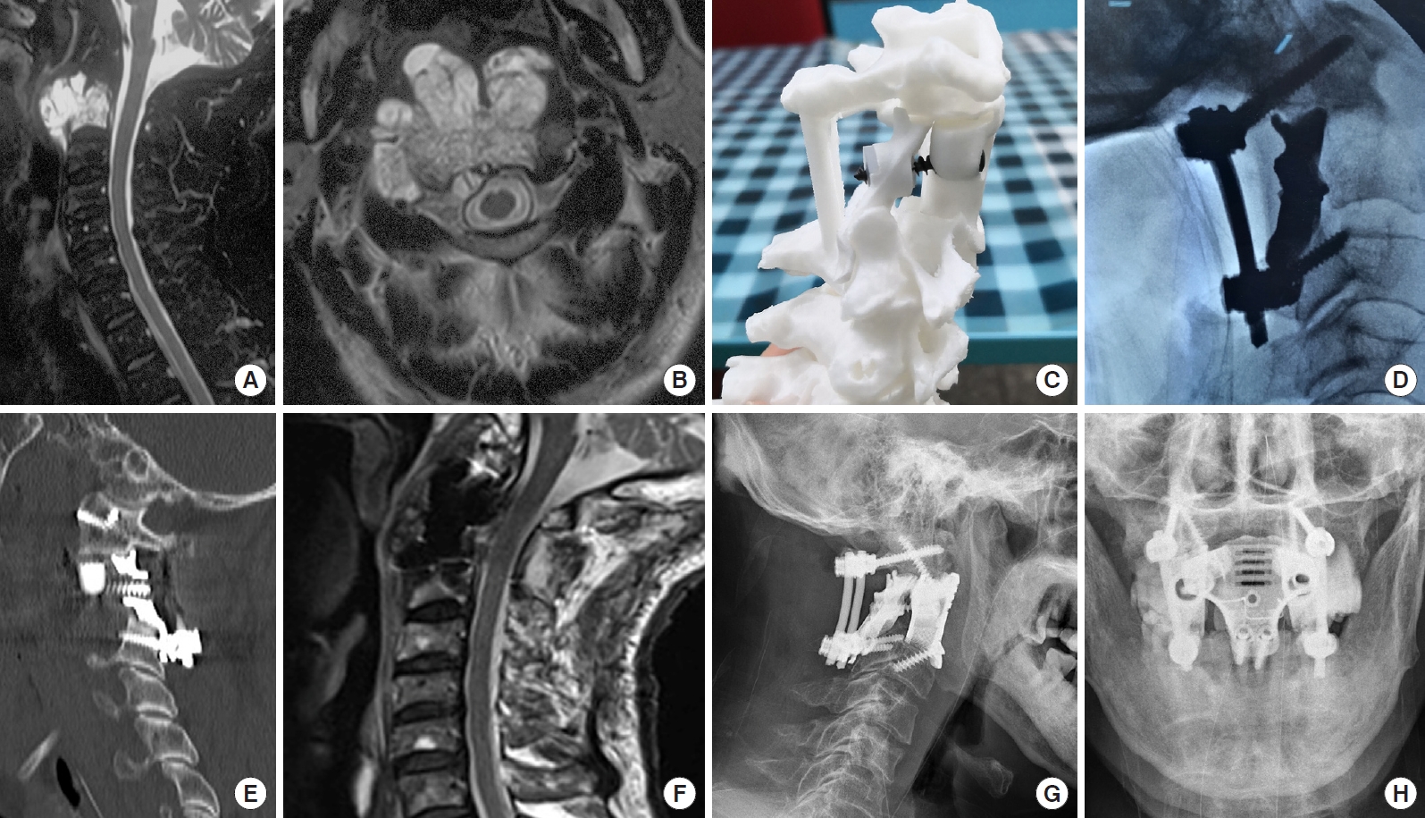
Imaging findings for case number 1. Sagittal contrast-enhanced magnetic resonance imaging (MRI) (A) and axial T2-weighted MRI (B) showing an axial tumor (Enneking stage IIB). The Weinstein-Boriani-Biagini stages were 5–10, A–D. Preoperative puncture pathology indicated chordoma. (C) A preoperative design of the 3-dimensional-printed axial lateral mass (LM) prosthesis. (D) An intraoperative image shows the implantation of the posterior LM prosthesis. (E) A postoperative sagittal computed tomography scan of the reconstruction shows that the LM prosthesis is in a good position and that the anterior screw was inserted into the anterior column and LM prostheses. (F) Postoperative sagittal T2-weighted MRI indicates good spinal canal volume. Postoperative lateral (G) and anteroposterior (H) radiographs of the cervical spine show that the LM prosthesis is well positioned.
Posterior cervical surgery was first performed to completely remove the posterior column structure of the axis, including the spinous process, lamina, inferior articular process and posterior wall of the axial transverse process foramen, to expose and dissociate the bilateral V3 segment of the vertebral arteries and C3 nerve roots, remove the anterior axis transverse process nodules in front of the vertebral artery, and remove the posterior 1/3 of the superior axis articular process above the V3 segment of the bilateral vertebral arteries. Finally, bilateral axial lateral mass prostheses were placed and fixed using a posterior screw rod system (Fig. 1C, D).
After complete disinfection of the oral and nasal cavities with iodophor, in a supine position, the patient's mouth was opened with a mouth opener, and the mucosa and muscle of the posterior pharyngeal wall were cut open. The tumor was visible on the axial surface, and part of the tumor was removed to fully expose the anatomical structure. The anterior atlas arch and axial odontoid process were removed, the C2/3 disc was removed, then the axial vertebral body was resected with the tumor. The dural sac was explored, and the tumor on the dural surface was completely removed. A 3D-printed axial prosthesis was placed, the lateral mass of the atlas was fixed cephalally with screws, and the upper margin of the C3 vertebral body was fixed caudally with screws. The anterior column prosthesis and the posterior lateral mass prostheses were fixed with a single screw, as the shared trajectory of the screw secured the 3-column fixed structure. The muscles and mucosa of the larynx wall were sutured in layers, and a nasal feeding tube was placed.
Wound healing of the posterior pharyngeal wall was determined using television fibrolaryngoscopy on day 7 postoperatively. Wound healing was satisfactory. The gastric tube was removed and a fluid diet was provided. Postoperative imaging showed a satisfactory match (Fig. 1E–H). After discharge, the patient received proton beam radiation therapy for residual disease and developed dysphagia after radiotherapy, without any other discomfort; the patient declined further imaging examination in the follow-up.
2) Case number 3
A 15-year-old male patient presented to our hospital with neck and upper limb pain and weakness in both lower limbs. Physical examination showed 4+ muscle strength grading of both lower extremities and knee reflex grading +++. MRI showed right C5/6 and C6/7 dumbbell-shaped tumors, involving C6–7 vertebral bodies (Fig. 2A, B). CT angiography revealed occlusion of the right vertebral artery. Preoperative puncture pathology showed a false-negative result. The tumor was removed, and cervical spine stability was reconstructed in 2 stages after tumor arterial embolism.

Imaging findings for case number 3. (A, B) Preoperative contrast-enhanced sagittal and axial T2-weighted magnetic resonance imaging shows a dumbbell tumor with C6/7 vertebral body involvement. Preoperative biopsy pathology indicated chordoma. (C) The lateral mass (LM) prosthesis was preoperatively designed based on the patient’s computed tomography (CT) data, and (D) the 3D-printed LM prosthesis was manufactured. (E) The first-stage posterior approach was used to remove the intraspinal tumor and reconstruct the LM structure. (F) A coronal CT scan of the reconstruction at 6 postoperative months shows that the LM prosthesis is in a good position. Dynamic radiographs taken in extension (G) and flexion (H) showed the stability of the implant.
In the first stage, resection of the intraspinal tumor and reconstruction of the lateral mass were performed via the posterior approach. We removed the cervical 6/7 spinous process, and the right semilamina and lateral masses to expose the epidural tumor invading along the foramina. The tumor had destroyed the transverse process and pedicle, and there was an abundant blood supply surrounding the vertebral artery. Intralesional excision of the intraspinal and partial paravertebral tumors was performed under microscopy. The right spinal nerves of C7–8 appeared to be well protected. An intraoperative rapid frozen section revealed a chordoma. A 3D-printed lateral mass prosthesis was implanted on the right side (Fig. 2C–E).
Seven days later, a secondary anterior paravertebral and vertebral tumor resection and an anterior column prosthesis reconstruction were performed. An anterior oblique incision was made to expose the anterior vertebral body. The tumor was visible on the spine surface. After part of the tumor was removed, C-arm x-ray fluoroscopy was used to determine the C5/6 and C6/7 intervertebral disc and related vertebral bodies. After the intervertebral discs and posterior longitudinal ligament were resected, the tumor together with the C6 and C7 vertebral bodies were then removed. An anterior vertebral body prosthesis of an appropriate size was placed between C5 and T1, and an anterior titanium plate was fixed with 4 screws. The internal fixation position of the C-arm was confirmed to be satisfactory, and a drainage tube was placed paraspinally.
The drainage tube was removed on postoperative day 1. Postdischarge, the patient did not receive proton beam radiation. Six-month follow-up imaging examinations indicated that the implant was in a good position (Fig. 2F–H). However, the tumor recurred at a later date.
3) Case number 4
A 62-year-old woman presented with pain and weakness in her left arm. MRI revealed a left C5–7 dumbbell-shaped tumor (Fig. 3A, B). Ultrasonography findings concerning the brachial plexus indicated left C7 thickening (left, 42 mm2; right, 18 mm2) compared with that on the contralateral side, decreased echo of the nerve bundle, and enhanced echo of the perineurium. Due to a previous history of breast cancer, metastatic cancer was highly suspected.

Imaging findings for case number 4. Enhanced sagittal (A) and axial T2-weighted (B) magnetic resonance imaging findings indicate left dumbbell tumors at C6/7 and C7/T1. (C) Tumor infiltration of the nerve root was observed intraoperatively, and (D) a lateral mass prosthesis was implanted following tumor resection. Postoperative lateral cervical radiograph (E) and sagittal computed tomography scan images of the reconstruction (F) show that the prosthesis was well positioned and that it was highly matched with the surrounding structures.
A posterior cervical approach was undertaken to expose the bilateral C5/T1 lamina and to excise the left lamina, the lateral mass, and the C6/7 pedicle. The tumor was attached to the dural surface and spinal nerve roots were involved. After resection, the spinal nerve root was swollen (Fig. 3C). A 3D-printed prosthesis was placed and fixed with a T1 pedicle screw and a C5 lateral mass screw (Fig. 3D).
Postoperatively, this patient reported no further pain in the left arm, and radiographic examinations taken prior to discharge showed that the prosthesis remained in a good position (Fig. 3E, F).
DISCUSSION
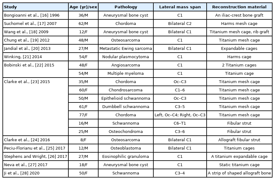
In spinal cord tumors, the incidence rate of spinal dumbbell tumors is reported to be approximately 18%, and is mainly located in the cervical segment [14]. Although total en bloc spondylectomy is not required, the lateral mass should be removed to expose the tumors in the intervertebral foramen. Internal fixation is needed to stabilize the cervical spine when > 50% of the facet joint is removed [15], but few studies have reported reconstruction of the lateral mass structure of the cervical spine (Table 2) [16-28]. For primary cervical vertebral tumors, reconstruction of spinal stability after spondylectomy is challenging. Most studies have reported reconstructing the vertebral structure of the anterior column only in conjunction with the posterior screw rod internal fixation system to maintain cervical spine stability [29,30].
Literature review concerning lateral mass reconstruction
Each vertebra of the upper cervical spine has particular morphological and biomechanical characteristics. The bilateral lateral mass of the atlas bears the entire weight of the head and, for this reason, reconstruction of the lateral mass structure is more common in cases of atlas lesions than in cases of axial lesions. Furthermore, the axial vertebra plays a unique role in the distribution of axial loads, transferring the weight carried through the bilateral superior facets to the 3 columns, namely, the anterior vertebral body and bilateral lateral mass joints [31]. We defined the lateral mass of the axis as a columnar structure connecting the facet from C1 to C3. Reconstruction of the lateral mass of the axial vertebra has rarely been reported, and reconstruction of the vertebral body of the anterior column appears to be the most common type involved. Stulik et al. [32] reported reconstruction of the C2 anterior column using a titanium cage connecting the anterior arch of the atlas or the basilar clivus to the C3 superior endplate. Ames et al. [33] reported 3 successful cases of reconstruction of the C2 anterior column using Steinmann pins and methylmethacrylate. Jeszenszky et al. [31] designed a C2 anterior column prosthesis through studying axial morphology. Xu et al. [6] and Hunn et al. [34] reconstructed the C2 anterior column vertebral body using 3D-printing technology. A common feature of all of these studies is the transfer of the axial load from bilateral columns of C1 lateral masses to the C3 anterior column, assisted using posterior fixation. In contrast to these studies, Suchomel et al. [17] reconstructed the axial’s 3-column structure. Bilateral axial lateral masses were reconstructed using titanium cages; however, the anterior column structure of the titanium cage directly connected the basilar clivus to the C3 vertebral body. While these studies reported successful reconstructions and integration, the reconstructions did not conform to the normal axial load transmission of the human body. The characteristics of the 3D-printed axial lateral masses designed in this study involved the articular surface area of the axis superior facet occupying one-third of the total inferior facet of the atlas, and the inferior facet directly connecting to the superior facet of C3. In combination with the anterior column prosthesis, the load carried through the bilateral C1 lateral masses was transferred to the anterior C3 vertebral body and the bilateral lateral mass joints to reconstruct the normal C2 structure and restore the normal two-column load bearing and 3-column load distribution.
The vertebrae of the subaxial cervical spine are ordinary and morphologically similar to one another. Unlike the facet joints of the lumbar spine, the posterior subaxial cervical facet carries 64% of the cervical axial load [35]. Various studies have reported a variety of strategies for reconstruction of the subaxial lateral mass. Ji et al. [28] reported a case of C3–4 lateral mass reconstruction using an allograft, and they performed a biomechanical evaluation of a cadaver specimen for the reconstruction of the subaxial lateral mass. Clarke et al. [23] reported 7 cases of subaxial lateral mass reconstruction using either titanium cages or ribs. However, more implants can increase risks during and after surgery. In the largest sample size series reported by Clarke et al. [23] (7 cases of lateral mass reconstruction), implant fixation system failure occurred in 2 patients. We consider that the reconstruction material (titanium cage) was an important reason for its failure. The titanium cage needs to be pruned intraoperatively and fitted over the articular process of adjacent segments. It is difficult to prune the titanium cage to an appropriate size by hand. Moreover, its use increases the risk of compression of the vertebral artery. Furthermore, the titanium cage has a cylindrical structure, which does not take the physiological curvature of the cervical spine into account. Thus, the application of a titanium cage cannot correct the physiological curvature of the cervical spine.
For resolving such challenges, 3D printing is a promising solution. The advantages of individualized 3D-printed prostheses are as follows. First, the design of the 3D-printed prosthesis is flexible and more individualized. These prostheses can completely reconstruct the multi-column mechanical support structure of the upper and subaxial cervical spine, in a manner that conforms more closely to the biomechanical characteristics of the normal human body, which theoretically avoid the shift in load above the bone defect to the screw and rod system. In addition, for cases involving a combined approach, the shared screw trajectory of the anterior column and lateral mass prosthesis can also be designed. These devices further improve the immediate stability of the prosthesis. Second, through the use of computer-aided design, 3D-printed prostheses possess high accuracy to precisely match the bone structure [36]. Compared with traditional structural reconstruction (titanium cage or fibular strut), there is no need for intraoperative trim or fibular graft, which reduces the difficulty of surgery and reduces operating time [11,37]. To better match the 3D-printed lateral mass prosthesis, we designed the lateral mass prostheses of different heights which facilitate the contact with the cephalic and caudal cervical structures and enable axial load bearing for some patients. In our patient group, the 3D-printed prosthesis was well matched during the operation, with prosthesis fitting error occurring in only one patient. Third, the microporous structure of the 3Dprinted prosthesis has an appropriate pore size and porosity to achieve long-term stability of the spine through osteoinductivity, and osseointegration [5-11]. Compared with polyetheretherketone (PEEK) or plasma sprayed porous titanium-coated PEEK, a 3D-printed porous titanium prosthesis possesses stronger biomechanical stability, mechanical strength, and better osseointegration [38]. Through reconstructing the lateral mass prosthesis, which acts as an interarticular bone graft bed, the graft space and bone conduction of the lateral mass structure of the cervical spine can be increased. However, 3D-printing technology has the following disadvantages. First, if more structures are removed intraoperatively, a prosthesis fitting error may occur, so it is necessary to carefully review the imaging data prior to surgery to determine the resection range and accordingly design the shape and size of the prosthesis. In this patient group, 1 patient had a prosthesis fitting error due to excessive intraoperative resection. Second, as 3D-printing technology is costly, the economic burden on patients is an issue. Third, the prosthesis has no locking device; hence, a posterior titanium rod and an anterior titanium plate were added in some patients to lock the screws. Thus, the long-term effects of screw loosening require further follow-up.
This study was limited in that there was an absence of biomechanical evaluations and a numeric value concerning axial load sharing was not determined. Future research is required to verify this understanding of load sharing using finite element analysis.
CONCLUSION
Reconstruction of the lateral mass structure is beneficial for restoring load transfer in the cervical spine under physiological conditions. A 3D-printed prosthesis is a good choice for reconstruction of the lateral mass to achieve fusion.
Notes
Conflict of Interest
The authors have nothing to disclose.
Funding/Support
This study received no specific grant from any funding agency in the public, commercial, or not-for-profit sectors.
Author Contribution
Conceptualization: ZC; Data curation: QJ, WD, JG; Writing - original draft: QJ; Writing - review & editing: Zu, FJ