Biportal Endoscopic Transforaminal Lumbar Interbody Fusion Using Double Cages: Surgical Techniques and Treatment Outcomes
Article information

Abstract
Objective
To describe the surgical techniques and the treatment outcomes of biportal endoscopic transforaminal lumbar interbody fusion (BETLIF) using double cages.
Methods
This study included 89 patients with 114 fusion segments between July 2019 and May 2021. One pure polyetheretherketone (PEEK) cage and 1 composite titanium-PEEK cage were used for interbody fusion. Clinical outcomes measures included visual analogue scale (VAS) scores for lower back pain and leg pain, Oswestry Disability Index (ODI), and Japanese Orthopedic Association (JOA) scores. Computed tomography (CT) of the lumbar spine 1 year postoperatively was used to evaluate the Bridwell interbody fusion grades.
Results
There were significant improvement in VAS for lower back pain from 5.2±3.1 to 1.7±2.1, VAS for leg pain from 6.3±2.5 to 1.7±2.0, ODI from 46.7±17.0 to 12.7±16.1, and JOA score from 15.6±6.3 to 26.4±3.2. The p-values were all <0.001. The average hospital stay was 5.7±1.1 days. The CT studies available for 60 fusion segments showed successful fusion (Bridwell grade I or grade II) in 56 segments (93.3%). Significant cage subsidence of more than 2 mm was only noted in 3 segments (5.0%). Complications included 1 dural tear, 2 pedicle screws malposition, and 2 epidural hematomas, in which 2 patients required reoperations.
Conclusion
BETLIF with double cages provided good neural decompression and a sound environment for interbody fusion with a big cage footprint, a large amount of bone graft, endplate preservation, and segmental stability.
INTRODUCTION
Lumbar interbody fusion (LIF) has been recognized as an effective surgical treatment for patients with refractory low back pain due to a variety of degenerative lumbar spinal disorders, including degenerative disc diseases and spondylolisthesis [1]. LIF can be done via anterior or posterior approaches. The posterior approach is familiar to the spine surgeons and is capable of directly decompressing stenosis. Among the various LIF techniques via posterior approach, transforaminal lumbar interbody fusion (TLIF) has gained its popularity for easier access to the disc space, lower risk of neural injury, and unilateral approach for insertion of the fusion cage and bone graft as compared to posterior LIF [2]. The fusion cages used in TLIF can be straight or crescent shapes made of different materials with equivalent clinical outcomes. However, pseudoarthrosis is still a big challenge, with an incidence ranging from 7% to 20% [2]. Using a large-sized cage may improve the fusion rate, but it is limited by the transforaminal approach and the small annular window.
Minimally invasive TLIF (MIS-TLIF) with a muscle sparing tubular retractor has evolved to reduce the approach related complications in traditional open surgeries, with decreased surgical morbidity, decreased length of hospital stay, and improved outcomes [3,4]. However, MIS-TLIF still poses a great challenge for the surgeon in neural decompression, removal of disc, and endplate preparation due to limited anatomic visualization and decreased haptic feedback. [2,4] Compared to the LIF via anterior approach, TLIF has a significant higher rate of cage subsidence, which may be attributed to the smaller cage footprint and endplate violation [5].
The biportal endoscopic technique is a revolutional minimally invasive technique that abandons the tubular retractor. It is performed through 2 independent portals with continuous irrigation of normal saline. The normal saline provides hydrostatic pressure to inhibit bleeding and carries away bone debris and oozing. The diameter of the endoscope is only 4 mm, thin enough to get access to the deep structures such as the contralateral lateral recess and the neural foramen. Combined with a high-definition endoscope, the biportal endoscopic technique provide a clear, bright, and magnified surgical field, enabling the surgeon to perform delicate surgical procedures with reduced risks of neural injuries.
Biportal endoscopic technique has been used for various MIS spinal decompression procedures, such as laminotomy for lumbar discectomy, unilateral laminotomy for bilateral decompression, and unilateral foraminotomy for decompression, all of which have demonstrated good clinical efficacy [6-9]. Recently, the biportal endoscopy technique were applied to LIF surgery in several pioneer studies [10-14]. These studies demonstrated the unique features of biportal endoscopic TLIF (BETLIF) including a clear and magnified surgical field, direct neural decompression, radical discectomy, and preservation of bony endplate. All these studies used a single TLIF cage for interbody fusion, and only 2 of them reported the fusion rate. Heo and Park [12] reported a 78.3% successful fusion rate as evaluated by serial x-ray, while Kang et al. [10] reported an 87.7% successful fusion rate as evaluated by computed tomography (CT) at 1 year postoperatively. However, there is still room for improvement. Additionally, since endplate preservation was repeatedly emphasized as an important feature of BETLIF, cage subsidence should be carefully evaluated.
In this study, we will describe our BETLIF technique, which uses 2 TLIF cages in a disc space. The purposes of this study are to evaluate the clinical and radiological outcomes, assessed using functional evaluation tools and CT, with a focus on the fusion rate and cage subsidence.
MATERIALS AND METHODS
1. Patient Selection
This case series included 89 consecutive patients who received 114 segments of BETLIF with double cages between July 2019 and May 2021 after being approved by the Institutional Review Board of Far Eastern Memorial Hospital (112021-E). To increase the cage footprint, we intended to use 2 composite titaniumpolyetheretherketone (Ti-PEEK) TLIF cages for interbody fusion. However, the cost of a composite Ti-PEEK TLIF cage is much higher than that of a pure PEEK TLIF cage, and it is not covered by the National Health Insurance (NHI) system in Taiwan. To compensate for the patient’s expenses, we replaced one composite Ti-PEEK TLIF cage with one pure PEEK cage, which is covered by the NHI. That is the reason why we used 2 cages of different materials.
The indications for BETLIF include mechanical lower back pain, radicular leg pain, or neurological symptoms/signs due to degenerative disc pathologies with persistent symptoms for more than 3 months and failure of conservative treatment. Double cages were used in all patients indicated for BETLIF, except for a few patients who could not afford the more expensive composite T-PEEK TLIF cage. Patients who had prior surgeries in their lumbar spines and patients who received BETLIF with a single cage were excluded from the study. The diagnoses were spondylolisthesis in 83 patients, degenerative disc disease in 4 patients, and degenerative scoliosis in 2 patients. All surgeries were performed by the author in a single medical center.
2. Evaluation of Clinical Data and Outcomes
The demographic and clinical data were retrieved from medical chart reviews. Treatment outcomes were evaluated before the surgery, at 1 month, 3 months, 6 months, 1 year after the surgery, and then every year thereafter. The outcome measures included the visual analogue scale (VAS) for lower leg pain and back pain, the Oswestry Disability Index (ODI) for disability, and the Japanese Orthopedic Association (JOA) scores for functional recovery. All patients had plain anteroposterior (AP) and lateral x-rays, dynamic flexion-extension lateral x-rays before the surgery, at 1 month, 3 months, 6 months, 1 year after the surgery, and then every year thereafter. All patients had a lumbar spine magnetic resonance imaging study before the surgery. CT of the lumbar spine was arranged at 1 year after the surgery to evaluate the fusion status. Reconstruction images on the sagittal and coronal planes were used to evaluate the formation of bridging bone. Fusion results were classified into grade I to grade IV using the Bridwell interbody fusion grading system [15]. Grade I or grade II fusion was defined as successful fusion. Cage subsidence was classified into “no subsidence,” “no more than 2 mm,” and “more than 2 mm,” depending on the depth of cage migration into the endplate on the sagittal or coronal CT images. Significant subsidence of more than 2 mm was considered clinically relevant [16].
Independent t-test was used to compare the continuous variables between groups. Chi-square test was used to compare categorical variables between groups. A p-value of < 0.05 was considered statistically significant.
SURGICAL TECHNIQUES
1. Anesthesia, Patient Positioning, and Draping
BETLIF is performed under endotracheal general anesthesia with the patient placed in the prone position on a Relton-Hall frame on a radiolucent spine table. The table should be adjusted to ensure free passage of the fluoroscope to obtain clear AP and lateral images. We also tilt the table head-up or head-down to keep the disc level of interest perpendicular to the floor for more ergonomic handling of the endoscope and surgical instruments.
Because the surgery is performed with continuous saline irrigation, a watertight draping is essential to prevent soaking and resultant hypothermia of the patient. We demonstrate the damconstruct draping method with a transparent covering hood for the fluoroscope (Fig. 1).
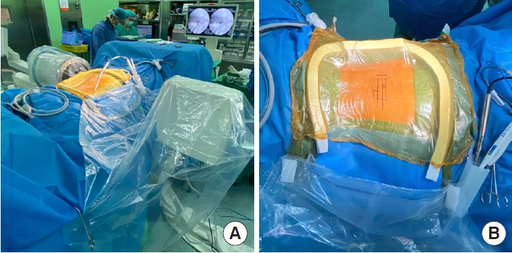
(A) The operating room setting, including the fluoroscope and its transparent covering hood. (B) A close-up photo demonstrates the dam draping method.
2. Localization and Skin Marking
After determining the disc level of interest using the lateral fluoroscopic image, all the other localizations and skin markings are drawn using the AP images. The skin markings include the disc line, the medial and lateral pedicle lines, the inferior pedicle line of the upper vertebra, and the superior pedicle line of the lower vertebra, as well as the skin incisions (Fig. 2). The skin incisions are about 2.5 to 3 cm long for a 1-segment fusion and 4 to 5 cm long for a 2-segment fusion. The skin incisions are 1 or 1.5 cm parallel and lateral to the lateral pedicle lines, which are also used for insertion of the pedicle screws. The offset distance varies according to the patient’s body habitus and can be estimated on the axial MR images in preoperative surgical planning.
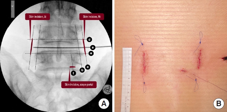
(A) The skin markings on the fluoroscopy: disc line (a), lateral pedicle line (b), incision line (c), inferior pedicle line (d), superior pedicle line (e), medial pedicle line (f). (B) The cosmetic surgical wounds after skin closure.
3. Approach and Creation of the Working Space
The approach is essentially the same as Waltse’s concept to minimize paraspinal muscle injury. After incising the deep fascia, we carefully dissect the intermuscular plane between the multifidus and longissimus dorsi down to the facet joint. Then, we use a dilator to bluntly dissect a small space over the lamina and facet joint. The endoscope is inserted into the working space through a separate small incision at the medial pedicle line. The triangulation of the endoscope and surgical instrument must be confirmed under fluoroscopy. With the inflow of normal saline, we use a radiofrequency wand (ArthroCare, Austin, TX, USA) to ablate the soft tissue to create the working space required for the following procedures.
4. Unilateral Laminotomy and Bilateral Decompression
We use the high-speed bur with a 4-mm coarse diamond ball tip (Primado II, NSK, Tokyo, Japan) as the main instrument for laminotomy. The starting point of unilateral laminotomy and bilateral decompression is the conjoined part of the spinous process and lamina (Fig. 3A). Use the high-speed bur to expose the cranial margin of the ligamentum flavum. Use the radiofrequency wand to dissect the facet joint. Use the small caliber curved osteotome to chop off the inferior articular process into small pieces (Fig. 3B). Harvest these small bone chips as local autografts. Use the Penfield dissector to detach the ligamentum flavum from the undersurface of the lamina. Use the bur to proceed with the sublaminar decompression to the contralateral lateral recess. Make sure that the underlying dura is well protected by the ligamentum flavum. Then move to the caudal end, using the bur to expose the caudal margin of the ligamentum flavum and decompress the ipsilateral lateral recess. Use the osteotome to chop off the tip of the superior articular process as local autografts. Use the Penfield dissector to lift the ligamentum flavum off the dura. Use the pituitary clamp to remove the ligamentum flavum as a whole piece or large pieces (Fig. 3C). Leave the lateral portion of the ligamentum flavum to protect the exiting nerve root. Use the osteotome or 2-mm Kerrison punch to remove the residual osteophytes and remnants of the ligamentum flavum. We prefer to use a 0° endoscope for initial laminotomy and contralateral decompression, then change to a 30° endoscope for the remaining procedures. The 30° endoscope provides a wider visual field and easier access to the disc space. Finally, use the bur to complete the total facetectomy and shape the transforaminal route (Fig. 3D).
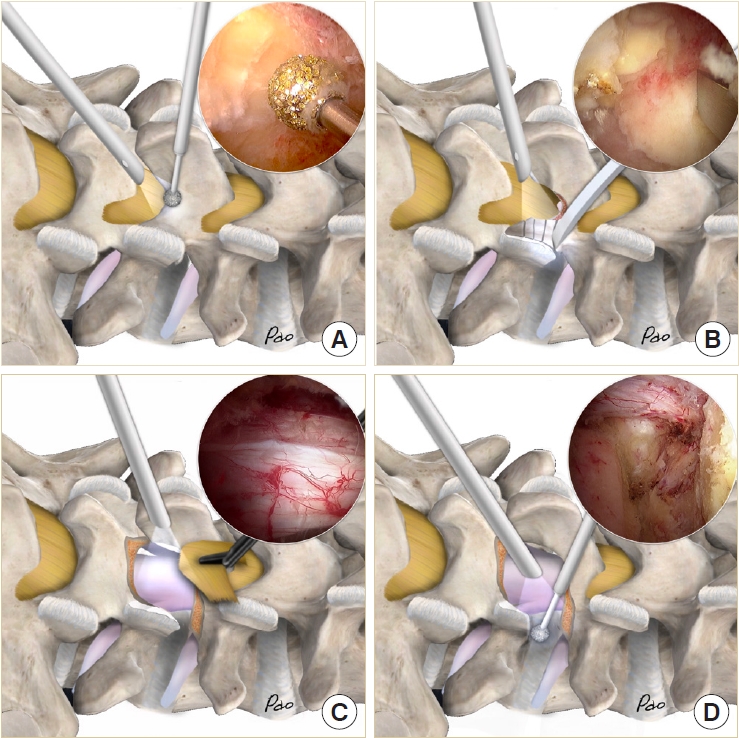
Illustrations and endoscopic images show the conjoined part of spinous process and lamina (A), use of the osteotome for resection of the inferior articular process (B), complete decompression and removal of the ligamentum flavum as a whole piece (C), resection of the superior articular process and creation of the transforaminal route (D).
5. Radical Discectomy and Endplate Preparation
The disk space must be large enough to accommodate 2 cages and a large amount of bone grafts. Therefore, the disk must be removed as radially as possible. Instead of using disk shavers or curettes for disk space preparation, we designed a new set of endplate strippers with 3 different angles to strip the cartilaginous endplate off the bony endplate (Fig. 4A). The different angles of the strippers are very helpful in accessing the deep contralateral corner in the disk space (Fig. 4B). The disk can be removed in large pieces along with the cartilaginous endplate and minimal injury to the bony endplate (Fig. 4C). We always insert the endoscope into the disk space to check the residual disk materials and ensure the integrity of the bony endplate (Fig. D4).
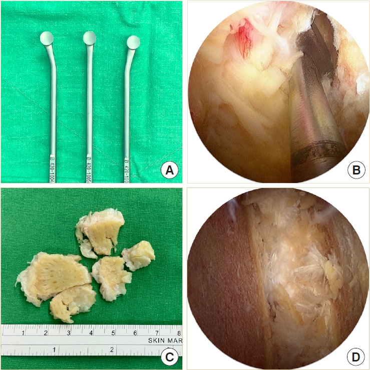
(A) The endplate strippers. (B) An endoscopic photo shows using the endplate stripper to separate cartilaginous from the vertebral body. (C) The cartilaginous endplates removed in large pieces. (D) An endoscopic photo shows radical discectomy and preservation of the bony endplate.
6. Cages and Bone Grafts Insertion
The composite Ti-PEEK cage (Combo-T, A-spine, Taipei, Taiwan) is composed of a PEEK core covered by a Ti plate on its superior and inferior surfaces. When the cage is inserted into a collapsed disc space, disintegration of the Ti plate may occur if it encounters excessive shear stress parallel to its interface. Therefore, we usually insert the solid pure PEEK cage (Reborn, Baui, Taipei, Taiwan) first to avoid such a possible complication (Fig. 5A). The cage height is evaluated using serial cage trials of 1-mm increment starting from 7 mm. When the cage trial is difficult to retrieve by manual force, the same height of the fusion cage is determined. We do not use the cage to restore its original disc height because that may pose excessive stress on the bony endplate and lead to cage subsidence. The first cage is inserted vertically through Kambin’s triangle, which is usually big enough for the cage trials and cage implants with no need to retract the dura or the traversing nerve root (Fig. 5B). The remaining lateral portion of the ligamentum flavum serves as a good protector for the exiting nerve root if it has not been removed yet. The cage should be inserted as anteriorly as possible. The first cage also serves as a spacer to maintain the disc space for impacting bone grafts into the remaining disc space. Bone grafts can be impacted into the disc space using a specially designed funnel (Fig. 5C). Then the second cage is inserted obliquely at an angle of about 45° to the plumb line (Fig. 5D). For the bone graft materials, we use demineralized bone matrix putty (SurFuse, HansBiomed, Daejeon, Korea) inside the cages and the mixture of demineralized bone matrix putty, local autografts, and beta-tricalcium phosphate outside the cages.
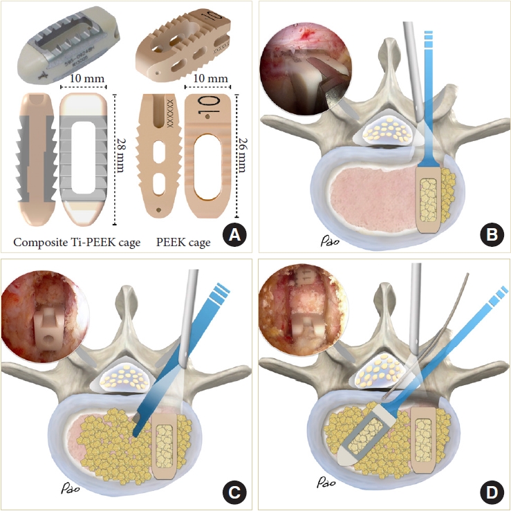
(A) The cages and their dimensions. (B–D) Illustrations and endoscopic photos demonstrate vertical insertion of the first cage, impaction of bone graft into the disc space maintained by the first cage, and 45° oblique insertion of the second cage.
We designed a cannulated dural anchor to protect the dura and the traversing nerve root while inserting the oblique cage (Fig. 6A). The surgeon gently retracts the dura and allows the assistant to tap the pin about 5 mm into the posterior annulus. The pin is made of shape memory alloy with a threaded anterior portion. The retractor can be easily removed by turning 180° and leaving the pin in situ to keep the dura retracted (Fig. 6B). The second cage is inserted obliquely into the disc space beside the pin. If indicated, the oblique cage can be inserted more horizontally to distract the contralateral disc space. Cage insertion is closely monitored under the endoscope (Fig. 6C). The final position of the cages is confirmed by fluoroscopy (Fig. 6D).
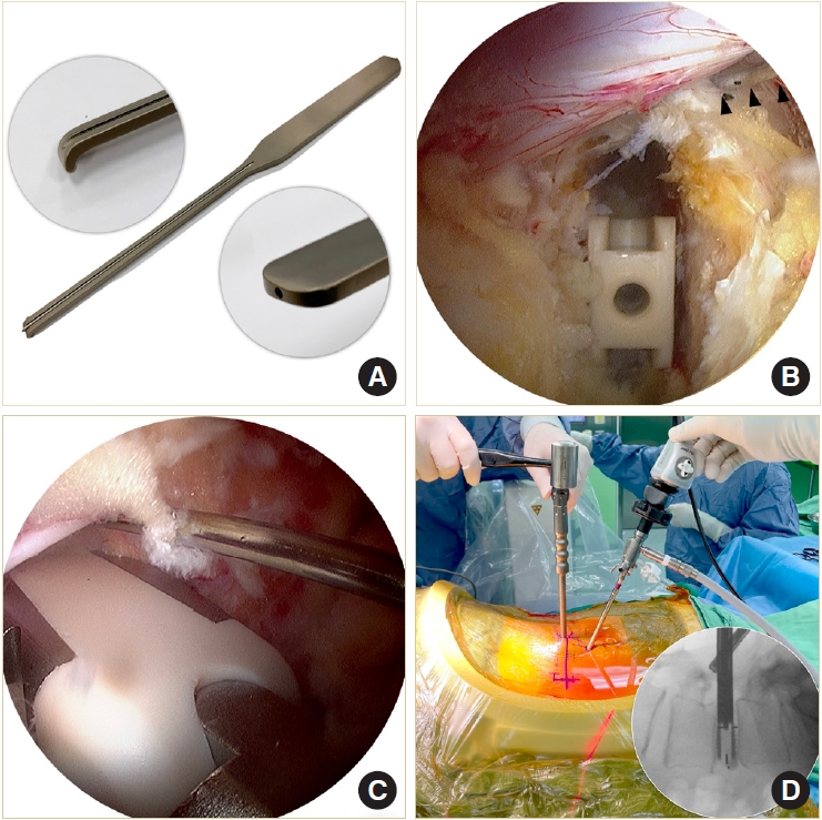
Illustrations and endoscopic photos show designs of cannulated dural anchor (A), use of the anchor to retract the dura (B), insertion of the oblique cage aside the anchor (C), and cage insertion without using any retraction tools (D).
7. Final Check Point
Use the endoscope to check the adequacy of neural decompression, including the cranial and caudal portions of the central canal, the contralateral lateral recess and traversing nerve root, the ipsilateral lateral recess and traversing nerve root, and the ipsilateral exiting nerve root. Temporarily stop the irrigation to check the dural pulsation and identify active bleeders. Use the radiofrequency wand to coagulate the bleeders or use bone wax to seal the cancellous bone. A drain tube is mandatory to reduce the risk of epidural hematoma.
8. Insertion of Pedicle Screws and Reduction of Spondylolisthesis
We use cannulated transpedicle screws with long reduction barrels (Smartloc, A-spine) for fixation and reduction of spondylolisthesis. Insertion of the pedicle screws is guided by fluoroscopy through the same surgical wounds and the intermuscular planes bilaterally. The contralateral pedicle screws are inserted in the same way through another skin incision. We always contour the connecting rods to obtain better lordotic alignment. Reduction of spondylolisthesis can be achieved by securing the caudal pedicle screws first and then pulling up the cranial vertebra using the cantilever technique. After confirming the final position of the pedicle screws, we secure the entire construct and break off the barrels to complete the instrumentation. The wounds are closed in layers. The skin incisions are closed with nonabsorbable subcuticular sutures and then secured with adhesive gel.
9. Postoperative Care
The drainage tube is kept in place for 24 hours after surgery. Wound pain is managed with regular oral Acetaminophen every 6 hours and intravenous Morphine (5 mg) injection as needed. One or 2 intravenous methylprednisolone (500 mg) infusions may be given to patients with transient neurological complaints or significant lower back soreness. Ambulation with a lumbo-sacral orthosis is permitted if the patient can tolerate the pain. The patient is typically discharged from the hospital on the third or fourth day after surgery.
RESULTS
This study included 17 males and 72 females with an average age of 64.7 years (range, 35–85 years). These patients received 114 segments of BETLIF, including 1-segment fusion in 66 patients, 2-segment fusion in 21 patients, and 3-segment fusion in 2 patients. L4–5 was the most frequently involved level, followed by L3–4, L5–S, and L2–3. The average follow-up period was 15.5 months (range, 12–31 months). The average hospital stay was 5.7± 1.1 days (range, 3–7 days). No patient required a blood transfusion. At the final follow-up, the VAS for lower back pain improved from 5.2± 3.1 to 1.7± 2.1, and VAS for leg pain improved from 6.3± 2.5 to 1.7± 2.0. The ODI improved from 46.7 ± 17.0 to 12.7± 16.1. The JOA score improved from 15.6± 6.3 to 26.4± 3.2. All these improvements were statistically significant from baseline with p < 0.001. Complications included 1 dural tear (1.1%), 2 pedicle screw malposition (2.2%), and 2 epidural hematomas (2.2%). Reoperation was required in 2 patients for evacuating the epidural hematoma and adjusting the pedicle screw. There was no pedicle screw loosening nor posterior cage migration. The demographic data and clinical outcomes were summarized in Tables 1 and 2.
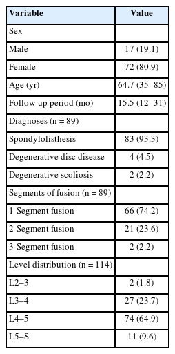
Demographic data (n=89)

Summary for clinical outcomes
Forty-six patients with 60 fusion segments underwent CT scan evaluation one year after surgery. Based on the Bridwell grading system, fusion results were grade I in 44 segments (73.3%), grade II in 12 segments (20.0%), and grade III in 4 segments (6.7%). Successful fusion was achieved in 56 segments (93.3%). Inside cage bridging bone (In-CBB) was observed in 44 segments (73.3%) and outside cage bridging bone (Out-CBB) was observed in 57 segments (95.0%). Of the 56 segments with successful fusion, 44 segments (78.6%) fused with both Out-CBB and In-CBB, 12 segments (21.4%) fused with only Out-CBB, and no segment fused with only In-CBB. Mild cage subsidence was observed in 11 segments (18.3%) and significant cage subsidence of more than 2 mm was observed in only 3 segments (5.0%). Pure PEEK cages had a significantly higher rate of subsidence than Ti-PEEK composite cages (p= 0.038) (Table 3).
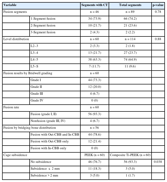
Summary for radiological outcomes by computed tomography (CT)
DISCUSSION
In this study, we present a minimally invasive technique for TLIF using biportal endoscopic technique and double cages. The treatment results show significant improvement in VAS score, ODI, JOA score, short hospital stay, and a low complication rate. No patient required blood transfusion. The radiological outcomes also show an excellent fusion rate with a very low incidence of cage subsidence.
Endoscopic LIF can be performed using uniportal or biportal endoscopic techniques [17]. The uniportal endoscopic technique is more technically demanding than the biportal one because the surgical instruments are confined to the rigid working channel, and the surgeon’s hands, surgical instruments, and endoscopic vision all work on the same axis. In contrast, the biportal endoscopic technique has no rigid working channel. The endoscope and surgical instruments are handled independently by the surgeon’s hands. Direct decompression of the central canal, bilateral lateral recess, and even bilateral neural foramen can be achieved under endoscopic guidance (Fig. 7) [14]. Traversing nerve root injury may be a concern when inserting the cage into the disc space; however, this concern can be solved by using a pin to gently retract the dura and the traversing nerve root [18].
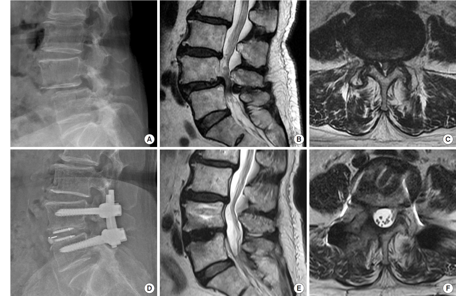
(A–C) Preoperative x-ray and magnetic resonance imaging (MRI) of the lumbar spine in a 64-year-old female patient with spondylolisthesis at L4–5 and associated severe canal stenosis. (D–F) Postoperative x-ray and MRI show restoration of the disc height, reduction of the spondylolisthesis, and good neural decompression with minimal soft tissue injury.
CT scan is the most reliable imaging modality to evaluate fusion status [19-21]. However, there are only limited studies using CT scans to evaluate fusion rates of endoscopic TLIF [22,23]. The fusion rate in our series is as high as 93.3%. The high fusion rate is attributed to radical disc removal, increased cage footprint by using double cages, and a large amount of bone grafts in the disc space (Fig. 8).

Postoperative computed tomography scan 1 year after a 2-segment BETLIF for spondylolisthesis at L4–S in a 71-year-old female show solid interbody fusion at both the composite Ti-PEEK (A–C) and the pure PEEK cage sides (D–F) with no cage subsidence at all. BETLIF, biportal endoscopic transforaminal lumbar interbody fusion; Ti, titanium; PEEK, polyetheretherketone.
To increase the contact surface between the graft and the vertebral bone, the removal of the disc should be as radical as possible to make room for bone graft and to expose the bony endplate for bone ingrowth. The biportal endoscopic technique provides a magnified and bloodless surgical field that enables the surgeon to remove the disc efficiently, with no need to struggle with continuous oozing anymore.
The amount of bone graft in the disc space is one of the detrimental factors for successful interbody fusion [24-26]. The bone graft inside the cages is usually of a small amount, or it would easily fall off when tapping the cage into the disc space. That makes bone graft outside the cage more important. However, because the outside cage bone grafts are usually inserted into the collapsed disc space before the cage, the amount of bone graft will be very small in the disc space. Sequential insertion of the double cages in our study allows more bone graft to be impacted in the disc space. We insert the first cage as the disc spacer, enabling the surgeon to impact more bone graft into the empty disc space before inserting the second cage. The postoperative CT scans show a substantial volume of fusion mass outside of the cages. A large amount of bone graft promotes bone fusion by increasing the contact between the bone graft and the exposed bony endplates. It also provides solid anterior support after successful fusion [27].
Cage subsidence is the most common complication following LIF. The incidence ranges from 15.9% to 70%, depending on the types of cages, surgical techniques, follow-up duration, and image evaluation tools [28]. Mild cage subsidence is considered a normal phenomenon of spinal fusion with no correlation to the clinical outcomes [29,30]. However, recent studies have observed that significant cage subsidence, more than 2 mm, is associated with postoperative disc height collapse and loss of lumbar lordosis, which may lead to recurrent symptoms and poor outcomes [28,31].
Endplate injury is recognized as a significant risk factor for cage subsidence [32-34]. However, few studies describe practical techniques to prevent this complication during endplate preparation. Considering that using conventional serial disc shavers and curettes might be too aggressive and cause endplate injury, we designed a set of endplate strippers with different angles to strip the disc along with the cartilaginous endplate off the bony endplate. We can closely monitor this process using an endoscope to avoid bony endplate injury. At the end of the process, we routinely insert the endoscope into the disc space to evaluate the extent of endplate preparation, ensuring that the disc is removed thoroughly, and the bony endplate is well-preserved.
A larger cage footprint reduces the possibility of cage subsidence by providing better segmental stability [33,35]. In posterior approach LIF, the size of the cage is limited by the presence of neural tissue in the path of the cage insertion. Overretraction of the neural tissue can lead to postoperative neurological symptoms or permanent neurological deficits. In our series, we use a “one vertical, one oblique” double-cage construct to double the footprint and reduce the risk of neurological complications from overretraction. Our newly designed cannulated dural anchor makes cage insertion much easier. This small pin not only prevents neural injury but also guides the insertion of the oblique cage. All these features make cage insertion no longer a blind process. The fluoroscope is only used to confirm the final position of the cages. Our double-cage construct safely increases the cage footprint by twice and distributes the stress more evenly on the endplate [36,37].
Ti alloy and PEEK are the most common materials used in interbody fusion cages. Ti alloy can enhance cell adhesion and bony ingrowth, but it can also increase subsidence caused by its stiffness relative to the vertebrae [38-41]. In contrast, PEEK has an elasticity close to that of bone and shows less subsidence than Ti cages. However, as an inert compound, PEEK results in lower fusion rates and osteolysis at the interface [41-43]. In our study, we used 1 composite Ti-PEEK cage and 1 pure PEEK cage for interbody fusion. The Ti interface showed better bony ingrowth and less osteolysis than the PEEK interface. The incidence of significant subsidence, more than 2 mm, was very low. However, the PEEK interface showed a significantly higher incidence of subsidence than the Ti interface, which contradicts the observations reported in the literature.
We always place the cages as anteriorly as possible and use the biplanar fluoroscope to confirm their final position. There are 2 major reasons for this. First, a posterior cage position is associated with cage subsidence and posterior cage migration [28,32,34,44-46]. Second, an anterior cage position is helpful for restoring the lumbar lordosis. To place the cage anteriorly, the disc space must be cleared in advance. Special attention must be paid to avoid iatrogenic injury to the retroperitoneal organs such as the aorta and the vena cava. The process must be monitored using the endoscope or the fluoroscope to avoid such catastrophic complications.
The current study has several limitations. First, it is a retrospective study with a small sample size, short-term follow-up, and no control group to compare the treatment outcomes to BETLIF with a single cage. Second, all surgeries were performed by a single spine surgeon who is experienced in minimally invasive and endoscopic spine surgeries in a large medical center, and the results may differ if surgeries are performed by another surgeon with a different level of experience. Third, CT scans were not available for every patient due to the retrospective design of this study, and bias does exist.
CONCLUSION
Minimal invasiveness is an inevitable trend in every surgical field. However, smaller surgical wounds should not compromise treatment results. Although minimally invasive TLIF using biportal endoscopic techniques is feasible, fusion rate and cage subsidence remain significant challenges. By combining the advantages of the biportal endoscopic technique and the doublecage construct, it is possible to improve fusion quality to the next level of excellence, with a high fusion rate and a low incidence of cage subsidence. Nevertheless, further studies are necessary to determine the optimal cage materials and designs, the significance of bone graft amount for a successful fusion, and to refine the surgical techniques.
Notes
Conflict of Interest
The authors have nothing to disclose.
Funding/Support
This study is supported by the research grant from Far-Eastern Memorial Hospital (FEMH-2023-C-065).