


INTRODUCTION
Cervicothoracic deformity encompasses a variety of pathologies that afflict the subaxial cervical spine and/or upper thoracic spine and result in considerable functional distress and morbidity [1,2]. Surgical correction of cervicothoracic deformities can result in considerable improvements in quality of life [3-6] and are accomplished through a variety of approaches and techniques based on severity and location of primary deformity. Subaxial cervical kyphosis can be corrected via anterior, posterior, or a combination of anterior and posterior approaches while deformity stemming from the upper thoracic spine is addressed primarily with posteriorly-based surgical techniques.
Realignment of severe kyphosis and deformity of the upper thoracic spine often necessitates a shortening operation, consisting of a 3-column osteotomy (3CO; pedicle subtraction osteotomy [PSO] vs. vertebral column resection [VCR]) [7,8]. Surgical techniques to correct kyphosis and shorten the spine through a 3CO can be accomplished via a variety of methods that rely on 3 major tenants: segmental compression, in situ bending, and cantilever bending. While effective in the majority of cases, these 3 corrective maneuvers often place screws under considerable stress and may result in screw pull-out and jeopardize deformity correction, particularly in elderly patients with poor bone quality. As such, a surgical technique that minimizes screw strain during deformity correction would be ideal. A unique method that fulfills these criteria is termed the “rail technique,” as it allows for en bloc shortening across accessory rods spanning the 3CO site. In the report presented herein, we outline the surgical steps of the “rail technique” in the context of correction of an iatrogenic, rigid, cervicothoracic deformity through a T4 VCR.
CASE REPORT
1. Clinical History
This case highlights a 65-year-old woman with a history of chronic pain, asthma, diabetes, hypertension, osteoporosis, depression, ovarian cancer in remission, and 8 prior spine operations (on chronic antibiotic suppression from prior lumbar discitis) who presented to the senior author’s clinic as a referral from an out-of-state spine surgeon with the chief complaint of an inability to maintain horizontal gaze and severe neck pain. On physical examination, her chin was thrust forward relative to her back, and her chin rested on her chest. Attempts at horizontal gaze were made at rotating her head to the left (through the C1–2 joints) and extending her skull (through the occiput–C1 joints), as she was unable to hold her head up with her hand under her chin. The forward thrust of her neck was partially correctable when lying supine, as her chin came off her chest, but her occiput could not rest on the table with active or passive attempts at neck extension. The posterior midline incision was healed without signs of infection. The neurological examination was normal.
Presenting radiographs demonstrated C5 to pelvis posterior instrumented fusion with subaxial cervical kyphosis (C2–7 Cobb 20°; C2 tilt 20°), grade 1 C3–4 anterolisthesis, markedly positive C2–7 sagittal vertical axis (cSVA; 8 cm), focal kyphosis at T3–5 (30°), increased T1 slope (50°), and a prior L3 PSO spanned by a 6-rod construct (Fig. 1A, Table 1). Lumbar sagittal alignment parameters included: pelvic incidence, 40°; lumbar lordosis, 46°; pelvic tilt, 24°; thoracic kyphosis (T2–12), 86° (Fig. 1A, Table 1). Global sagittal balance, as measured by the C7–S1 SVA, was 0 cm (Fig. 2A). Coronal balance, as measured by the central sacral vertical line, was 1.8 cm to the left (Fig. 1B, Table 1). This cervicothoracic deformity was a consequence of a prior proximal junctional failure and kyphosis (PJF/PJK) at T4 above a prior T5 to pelvis that was stabilized in situ.
Preoperative evaluation included a full spine computed tomography (CT) myelogram, dual-energy x-ray absorptiometry (DEXA) scans of the forearm and hips, pulmonary function tests (PFTs), and a cardiac stress test. CT myelogram demonstrated no neural compression and haloing around the left C5 and C6 lateral mass screws and the T1 pedicle screws (Fig. 1C). Additionally, it was noted that there was a grade 1 anterolisthesis at T3–4 with a compromise of the superior anterior endplate of T4 (Fig. 1D). DEXA scan demonstrated T-scores within normal range (-1.5 to 0) in the distal radius, femoral neck, and femoral heads. A moderate obstructive pattern and a mild deficit of oxygen diffusion capacity were noted on PFTs. The cardiac stress test demonstrated no ischemic changes and an ejection fraction of 78%.
Given the patient’s severe functional disability (Table 2), operative intervention was recommended. While the patient’s cervicothoracic deformity represented a combination of subaxial cervical kyphosis (high C2 tilt and kyphotic C2–7 Cobb angle) and upper thoracic kyphosis (high T1 slope), the primary driver of the deformity appeared to be the focal kyphosis at T4 (area of prior PJF/PJK). As such, a revision and extension of the posterior instrumented fusion from C2 to T10 with a posterior VCR at T4 and Ponte osteotomies at C4–5, C5–6, C6–7, and T1–2 was planned. As the focal kyphosis from T3 to T5 was 30° (measured from the inferior endplate of T3 to the superior endplate of T5) (Fig. 1D), the goal of correction was to horizontalize the inferior endplate of T3 relative to the superior endplate of T5 to achieve 30° of correction, which was expected to result in a correction of the T1 slope to approximately 20°, normalize the cSVA (< 4 cm), and decrease the compensatory occiput–C2 angle. Improvement of the subaxial cervical kyphosis was anticipated to be less dramatic with this posterior-only approach, given the degree of ankylosis through the discs from C3 to C7.
2. Operation
The patient was brought to the operating room and underwent general anesthesia and endotracheal intubation. After placing Gardner-Wells (GW) tongs in the cranium, she was turned prone with 6.8 kg of biplanar rope traction attached to the GW tongs [9]. After the entire cervical and thoracolumbar spine were prepped and draped in a sterile manner, the incision was made, and subperiosteal dissection was carried from C2 to T10. The prior instrumentation was exposed. The rods bilaterally were cut between T10–11. The screws were then removed from C5–T3 and T5–10. Inspection of the spine was notable for focal kyphosis at T4 and nonunions at C5–6, C6–7, and C7–T1 area as well as in the mid-thoracic spine. New pedicle screws were placed using a free-hand technique at T2, T3, T5, T6, T7, and T8. With the assistance of lateral fluoroscopy, lateral mass screws were placed at C3, C4, and C5, and pedicle screws were placed at the C2 pedicle. No screws were placed at C6, C7, T1, T9, or T10. Ponte osteotomies were then performed at C4–5, C6–7, and C7–T1 by removing the interspinous ligament, the ligament flavum, and facet joints bilaterally. Attention was then turned to the VCR at T4.
A laminectomy was performed from the T3 pedicles to the T5 pedicles. Complete facetectomies were performed bilaterally at T3–4 and T4–5, which exposed the nerve roots at T3 and T4 bilaterally. The T4 nerve roots were then ligated with silk sutures and cut. The T4 ribs were then exposed laterally, and the ribs were cut and disarticulated from the transverse processes. The lateral portion of the T4 body was exposed bilaterally through lateral extracavitary approaches. Malleable retractors were then placed around the T4 body, bilaterally protecting the visceral structures anteriorly and laterally.
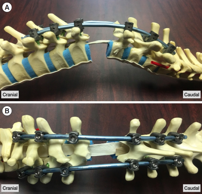
At this point, placement of a temporary stabilizing rod was placed on the contralateral side from which one was performing the posterior VCR. A temporary 5.5-mm cobalt chrome rod was secured into the tulip heads of the pedicle screws from T2 to T8 on the left side while working on the right side. The T4 vertebral body was decancellated with a diamond-tip burr, and curettes were used to remove the body further to the anterior cortex - the posterior cortex remained intact. The inferior endplate of T3 was exposed by removal of the T3–4 disc. This was then followed by removal of the T4–5 disk, so the superior endplate of T5 was exposed. These steps were then repeated on the left side after the left rod was removed, and a new final 5.5-mm cobalt chrome rod was secured into the tulip heads of the pedicle screws from T2 to T10 on the right side. The anterior and posterior cortices of T4 were then removed and care was taken to ensure the spinal cord and dura were free anteriorly with no connection anteriorly or posteriorly. At this point, the second final 5.5-mm cobalt chrome rod was secured on the left from T2 to T10 (Fig. 2). To prepare for shortening through the VCR site using the “rail technique,” the following steps were followed.
3. Rail Technique
1) Step 1
Accessory rods placed laterally on each side and connected to the central rods with open-open (“W”) rod-rod connectors cranial to the VCR site between T2–3 (upper instrumented vertebra [UIV]+2/UIV+1) and T1–2 (UIV+3/UIV+2) and cranial to the VCR site between T5–6 (UIV-1/UIV-2) and T6–7 (UIV-2/UIV-3) (Fig. 3). (Note: the accessory rods need not be in the same plane as the midline rods).
2) Step 2
All the set screws in the midline/main rod cranial to the osteotomy site are tightened (Fig. 3A).
3) Step 3
On the W-connectors cranial to the 3CO that connects the accessory rod to the midline/main rod, the set screws on the midline/main rod and the accessory rod should be tightened (Fig. 3A).
4) Step 4
All the set screws in the midline/main rod cranial to the osteotomy site is loosened (set screws are retained in the tulip heads) (Fig. 3B).
5) Step 5
On the W-connectors cranial to the 3CO that connects the accessory rod to the midline/main rod, the set screws on the midline/main rod and the accessory rod should be loosened (Fig. 3B).
6) Step 6
The head is lifted through the GW tongs, and the weights are switched from the flexion rope to the extension rope, as previously described by Karikari et al. [9].
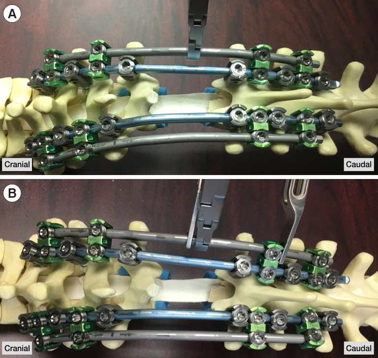
7) Step 7
A rod holder is secured to the accessory rod on one side (i.e., right) cranial to one of the rod-rod connectors cranial to the osteotomy site (Fig. 4A). Compression is then applied across the rod holder and the rod-rod connector (Fig. 4B) (Supplemental video clips 1, 2).
This, in effect, results in the locked proximal segment translating distally in an en bloc fashion and shortening through the osteotomy site by sliding along the rods (i.e., “rails”) (Supplemental video clips 1, 2). (Note that the kyphosis correction in the video is not as robust as what can be achieved clinically. This is likely a result of the video being performed on a sawbones model, which lacks surrounding soft tissue attachments to the spine and is void of any anterior column support).
8) Step 8
The set screws on the cranial accessory rods’ cross-connectors and midline/main rod are then tightened.
9) Step 9
The above steps are then repeated on the contralateral side. All set screws are tightened provisionally.
After the osteotomy site was shortened using this technique, a small gap within the T4 osteotomy site was filled in with a Harms cage (14 mm × 13 mm), local autograft, and allograft. Ensuring that all set screws on the right and left sides were secured proximally and distally to the osteotomy site in the midline/main rods, all the set screws on the accessory rods were loosened and removed. The distal aspects of the rods were also connected to her prior thoracolumbar instrumentation with side-to-side connectors. Attention was then turned to correction of the subaxial cervical spine.
Two 5.5-mm titanium rods were cut to size, contoured, and placed into the cervical spine from C2 to T1. Working from proximal to distal, the screws were secured – this cantilever technique allowed for correction of some of the subaxial kyphosis through the Ponte osteotomies at C4–5, C6–7, and C7–T1. The distal ends of the 5.5-mm titanium cervical rods were then connected to the 5.5-mm cobalt chrome rods in the thoracic spine with rod-rod connectors. To improve the cervical and cervicothoracic sagittal alignment further, compression was applied across these connectors bilaterally. Radiographs were obtained checked to ensure the adequacy of correction.
The wound was then thoroughly irrigated with saline, and then decortication was performed from C2 to T10. Bone graft and 2 large kits of rhBMP-2 (off-label use) were cut into long strips and placed in the cervical and thoracic spine. A drain and vancomycin powder were placed subfascially. The incision was closed in layers. The patient was turned to a supine position, placed in a collar, extubated, and taken to the recovery room in good condition. At the end of the operation, there was no change in neuromonitoring signals, and her neurologically examination was intact.
4. Follow-up
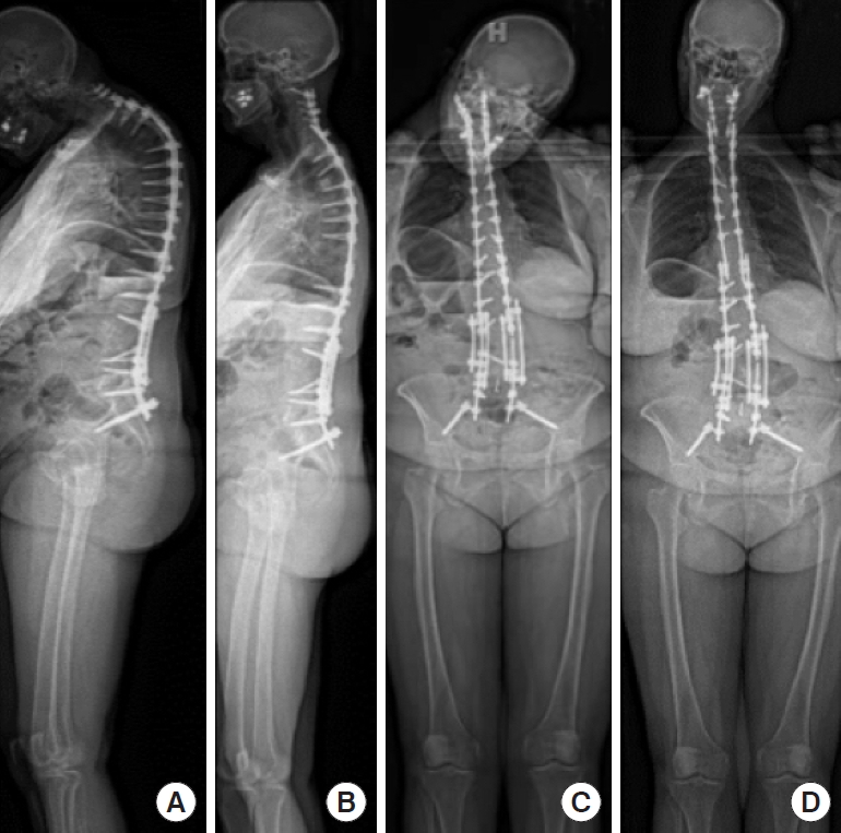
After an uneventful inpatient hospital course, she followed up at regular intervals. At 6 months postoperatively, she reported doing extremely well. While back pain remained high (visual analogue scale 6, Oswestry Disability Index [ODI] 36), she reported significant improvements in Scoliosis Research Society-22 (SRS-22) scores for self-image, mental health, satisfaction, and subscores compared to preoperative values (Table 2). At her 1-year postoperative visit, she also reported being “very happy” with the result because of her excellent alignment. Compared to 6-month postoperation, she reports higher SRS22 scores for function, mental health, and subscore and similarly improved SRS-22 scores for self-image and satisfaction compared to her preoperative state (Table 2). ODI scores were also better than preoperation (24 vs. 20). She reported no neck pain, and she had weaned down on her high-dose narcotics. Radiographs demonstrated excellent restoration of cervical sagittal alignment (C2–7 Cobb, 4.4°; C2–7 SVA, 2.7 cm), T1 slope (26°), thoracic kyphosis (45°), focal T3–5 kyphosis (7°), and global sagittal alignment (C7–S1 SVA 0 cm) (Table 1, Fig. 5).
DISCUSSION
Three-column osteotomies in the upper thoracic spine are powerful techniques to correct cervicothoracic deformities [7,8]. Shortening and deformity correction across the 3CO can be accomplished by a variety of surgical techniques. In this case report, we introduce and highlight the surgical steps of a unique shortening technique that we term the “rail technique,” in the context of correction of an iatrogenic, rigid, cervicothoracic deformity through a T4 VCR. In addition to describing the surgical technique, we also present the patient's clinical and radiographic outcomes.
The most common techniques to correct kyphosis in the thoracic spine are cantilever bending, in situ bending, and segmental compression. While these techniques can be used successfully in the majority of cases, there are situations in which their use is less than ideal. For example, cantilever bending is particularly beneficial when correcting kyphosis over multiple spinal segments, but less effective and safe when kyphosis correction is focal. Cantilever bending can also jeopardize screw fixation and lead to screw pull-out in patients with poor bone quality and when deformity correction is substantial. While segmental compression can achieve nice kyphosis correction focally, it runs the risk of screws ploughing through the pedicles in rigid spines with poor bone quality. In situ bending is a very common technique that is suited for fine-tuning maneuvers of deformity correction, as it can place considerable stress at the bone-implant interfaces. Another complicating phenomenon of in situ bending is the “spring back” of the rod that can prevent preserving the acquired deformity correction after removal of the bending force [10]. Given each of these 3 technique’s potential limitations, the “rail technique” is an ideal alternative, as it allows for powerful focal kyphosis correction while minimizing stress on the bone-screw interfaces.
At its essence, the “rail technique” utilizes accessory rods to shorten the spine en bloc across a 3CO by sliding along the midline/main rods (attached to tulip heads). Thus, the term “rail” refers to the accessory rods as well as the midline/main rods. To set-up for performing the “rail technique,” one first places the final midline rods across the osteotomy site and then places 2 accessory rods across the osteotomy site (one on each side). The key to the “rail technique” is to understand which set screws cranial and cranial to the osteotomy site need to be tightened and kept loose. To achieve the desired shortening, the first step is to ensure all the set screws on the midline/main rod and cross-connectors to the accessory rods cranial to the 3CO should be tightened and all the set screws in the midline/main rod and cross-connectors to the accessory rods cranial to the 3CO should be loosened. The accessory rods’ primary purpose is to be the rod on which compression is directly applied. By using a compressor across a rod holder on the accessory rod, and cross-connector cranial to the 3CO on the accessory rod compression across the 3CO is smooth and controlled, given the compression is occurring across multiple rods.
The rail technique provides several advantages relative to traditional corrective techniques. The use of accessory rods and our “rail technique” provide and allow for the following:
(1) Very controlled compression across a 3CO given that the 3CO is spanned by 4 rods at the time of shortening. This helps minimize translation across the 3CO site.
(2) Asymmetric compression across a 3CO, which makes it particularly useful when correction of concomitant sagittal and coronal deformity is desired and required.
(3) Minimizes bone-screw interface forces, as it does not rely on any direct compression across any individual screws. Instead, by sliding along the “rails,” the compressive forces are shared and transferred across multiple spinal levels and only on the rods. This is extremely beneficial in patients with poor bone quality.
(4) A final construct that consists of 4 rods that span a 3CO, which can act as one’s final construct. This can help minimize multiple rod exchanges. Keeping the accessory rods in place for the final construct also increases the overall metal density across the 3CO site, which may reduce the risk of delayed rod fracture.
(5) Minimizes and potentially avoids the use of in situ bending. This, in turn, prevents any “oops” moments that may occur over an exposed spinal cord.
CONCLUSION
The advantages mentioned above make the “rail technique” a safe and effective method for shortening over a 3CO to correct cervicothoracic deformity. Despite these advantages, its use is not intended to replace the other important deformity corrective maneuvers. Instead, we anticipate this case report will demonstrate to surgeons that the “rail technique” would be a nice addition to any spine surgeon’s surgical toolbox when correcting cervicothoracic deformities.


")